
Coating roller of roller coater

A technology of coating roller and roller coater, which is applied to the device for coating liquid on the surface, coating and other directions, can solve the problems of uneven surface temperature of coating roller, difficult heat dissipation of heating elements, and easy damage of heating elements, etc. The effect of fast heat conduction, quality improvement and cost saving

Inactive Publication Date: 2014-07-30
博可机械(上海)有限公司
View PDF8 Cites 2 Cited by
  • Summary
  • Abstract
  • Description
  • Claims
  • Application Information

AI Technical Summary

Problems solved by technology

[0004] The existing roller coater is roughly divided into two parts: the upper melt glue coating part and the lower chain roller conveying part. The melt glue and glue coating are mainly completed by using a heated coating roller. The heating of the existing coating roller is generally The internal heating method of the roller is adopted, and the internal heating method of the roller is too high, the heating element is not easy to dissipate heat, the heating element is easily damaged, and the maintenance is difficult. At present, there are also external heating methods, which generally conduct heat to the coating roller through both ends. , or through the heat conduction medium to conduct heat to the center of the coating roller. These heat conduction methods will cause uneven temperature on the surface of the coating roller due to the positional relationship of heat conduction, or the temperature will be low when transferring heat to the surface of the coating roller, resulting in large heat loss and high cost.

Method used


Image

  • Coating roller of roller coater
  • Coating roller of roller coater
  • Coating roller of roller coater

Examples


Embodiment

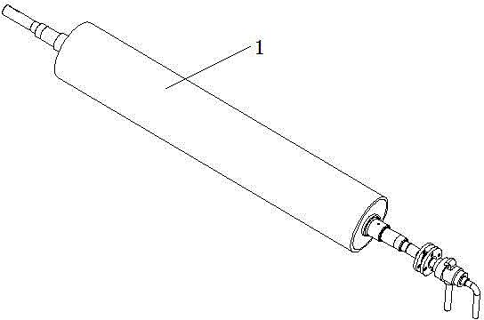
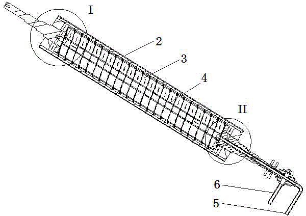
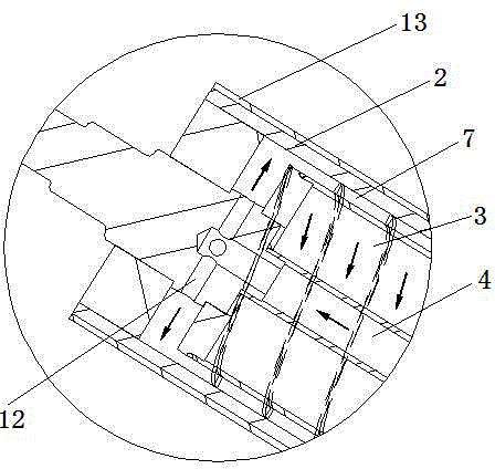
[0022] Example: as attached figure 1 , with figure 2 , with image 3 And attached Figure 4 As shown, a coating roller for a roll coater includes a roll body 1, the roll body includes a roll shell 2 and a roll core 3, the roll shell and the roll core are nested with each other, the center of the roll core is penetrated to form a central passage 4, and the roll core The outer surface is provided with a double helix thread, the outer surface of the roller core cooperates with the inner surface of the roller shell to form a double helical channel 7, and one end of the roller body is provided with an inlet pipe 8 and an outlet pipe 9, and the inlet pipe and the outlet pipe are concentric Pipe, the input pipe is the input channel 10, the output channel 11 is formed between the introduction pipe and the output pipe, the input channel is connected to the central channel, the output channel is connected to the double helix channel, and the other end of the roller body is provided w...


PUM


Abstract

The invention discloses a coating roller of a roller coater. The coating roller comprises a roller body, wherein the roller body comprises a roller shell and a roller core; the roller shell sleeves the roller core; a central channel is formed in the center of the roller core in a penetration manner; a multi-helix thread is arranged on the outer surface of the roller core; the outer surface of the roller core is matched with the inner surface of the roller shell to form a multi-helical channel; a guide-in pipe and an output pipe are arranged at one end of the roller body and are concentric pipes; an input channel is arranged in the guide-in pipe; an output channel is formed between the guide-in pipe and the output pipe; the input channel is communicated with the central channel; the output channel is communicated with the multi-helical channel; a connection head is arranged at the other end of the roller body and is communicated with the central channel and the multi-helical channel. By virtue of heat conduction of the coating roller of the roller coater, the surface of the roller shell is heated at uniform temperature, the temperature difference change of all parts is small, the roller coating quality of the roller coater is greatly improved, a heating medium is clung to the surface of the roller shell for heat transfer, the heat conduction speed is high, the heat loss is low, and the cost is lowered.

Description

[0001] technical field [0002] The invention relates to a roll coater component, in particular to a roll coater coating roller. [0003] Background technique [0004] The existing roller coater is roughly divided into two parts: the upper melt glue coating part and the lower chain roller conveying part. The melt glue and glue coating are mainly completed by using a heated coating roller. The heating of the existing coating roller is generally The internal heating method of the roller is adopted, and the internal heating method of the roller is too high, the heating element is not easy to dissipate heat, the heating element is easily damaged, and the maintenance is difficult. At present, there are also external heating methods, which generally conduct heat to the coating roller through both ends. , or conduct heat to the center of the coating roller through the heat conduction medium. These heat conduction methods will cause uneven temperature on the surface of the coating ...

Claims


Application Information

Patent Timeline
Patent Type & Authority Applications(China)
IPC IPC(8): B05C1/08
Inventor 金艳明汪新军熊飞
Owner 博可机械(上海)有限公司
Learn More