Molten steel flow divider bracket

The technology of a molten steel diverter and an angle steel is applied to the structure of the bracket and the structure field of the bracket of the molten steel diverter. The effect of production costs

Active Publication Date: 2014-07-30
张家港市欧微自动化研发有限公司
View PDF5 Cites 3 Cited by
  • Summary
  • Abstract
  • Description
  • Claims
  • Application Information

AI Technical Summary

Problems solved by technology

[0003] However, when pouring molten steel, the molten steel in the cavity of the ingot mold often overflows, flows on the cuboid casting support, and even penetrates into the holes of the cuboid casting support. It is easy to condense with the inner wall of the hole of the bracket), it is difficult to take out the ingot mold from the hole of the cuboid casting bracket, and the cost of the bracket is high, which brings great inconvenience to the use

Method used


Image

  • Molten steel flow divider bracket
  • Molten steel flow divider bracket
  • Molten steel flow divider bracket

Examples


Embodiment Construction

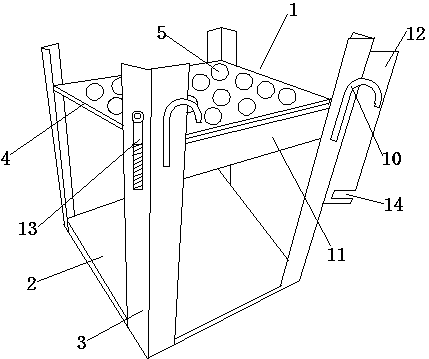
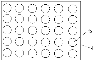
[0025] The support of the molten steel diverter, the support 1 is composed of a base plate 2 and support columns 3 respectively arranged on the four corners of the base plate. The upper part of the bracket is provided with a positioning plate 4 parallel to the bottom plate, the positioning plate is provided with a positioning hole 5 for placing the ingot mould, a connecting beam 11 is provided between two adjacent support columns, and insulation cotton baffles are provided on the four sides of the support Board, the middle and upper part of the outer surface of the bracket is provided with a hook 10.

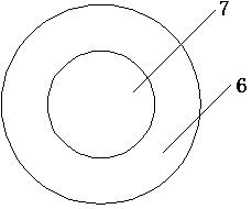
[0026] The positioning holes on the positioning plate are distributed in a dot matrix, and the ingot mold 17 is placed in the positioning holes. The ingot mold is cylindrical and has a cavity 18 inside. The aperture of the positioning holes is equal to the outer diameter of the ingot mold, and the ingot mold is inserted and fixed. in the positioning hole. Positioning strip 15 i...


PUM


Abstract

The invention discloses a molten steel flow divider bracket, and belongs to the technical field of steelmaking equipment. The molten steel flow divider bracket is formed by connecting a bottom plate, and support posts which are respectively arranged at the four corners of the bottom plate, wherein a positioning plate which is parallel to the bottom plate is arranged at the middle upper part of the bracket; positioning holes for placing ingot molds are formed in the positioning plate; lock devices are respectively arranged on the opposite sides of the upper part of the bracket; each lock device consists of a steel angle, a bolt and a nut; the steel angle and the bolt are respectively arranged on two support posts on the same side surface of the bracket; one end of each steel angle is hinged to the corresponding support post; a gap is formed in the other end of the each steel angle; one end of the bolt is hinged to the corresponding support post; the other end of the bolt is connected and fixed to the gap of the corresponding steel angle through the corresponding nut. The molten steel flow divider bracket is simple and reasonable in structure and easy to produce and manufacture; the problem of overflow of molten steel is solved, and the ingot molds are not easily condensed with the bracket, so that the production efficiency is improved, the production cost is reduced, and the molten steel flow divider bracket has broad market space.

Description

technical field [0001] The invention relates to a structure of a bracket, in particular to a structure of a bracket of a molten steel diverter, and belongs to the technical field of steelmaking equipment. Background technique [0002] In the steelmaking process, it is often necessary to flow the smelted molten steel into the cavity of the ingot mold through the molten steel distributor. The ingot mold is cylindrical and has a cavity inside. The molten steel splitter is generally placed on the molten steel splitter bracket. The existing molten steel splitter bracket is generally in the shape of a cuboid casting. There are multiple holes for placing the ingot mold in the cuboid. The through holes on the molten steel splitter and the position of the ingot mold cavity correspond. When in use, pour molten steel directly into the molten steel distributor, and the molten steel flows into the cavity of the ingot mold through the through hole on the molten steel distributor, and tak...

Claims


Application Information

Patent Timeline
Patent Type & Authority Applications(China)
IPC IPC(8): B22D35/04
Inventor 卞志鹏计永茂韦华卞兴来
Owner 张家港市欧微自动化研发有限公司
Why Eureka
Try Eureka