Mortar tank with automatic dust-collecting function

A mortar tank and automatic technology, applied in the directions of batch storage, clay preparation device, mixing operation control device, etc., can solve the problems of inability to collect dust and occupy operating space, and achieve the solution of dust overflow, uniform discharge, and prevention of mortar segregation. Effect

Active Publication Date: 2019-04-30
ZHEJIANG UNIV
View PDF5 Cites 1 Cited by
  • Summary
  • Abstract
  • Description
  • Claims
  • Application Information

AI Technical Summary

Problems solved by technology

However, this device needs to place an additional water container, occupying the operating space, and at the same time cannot recover the dust, so as to achieve zero discharge

Method used


Image

  • Mortar tank with automatic dust-collecting function
  • Mortar tank with automatic dust-collecting function
  • Mortar tank with automatic dust-collecting function

Examples


Embodiment 1

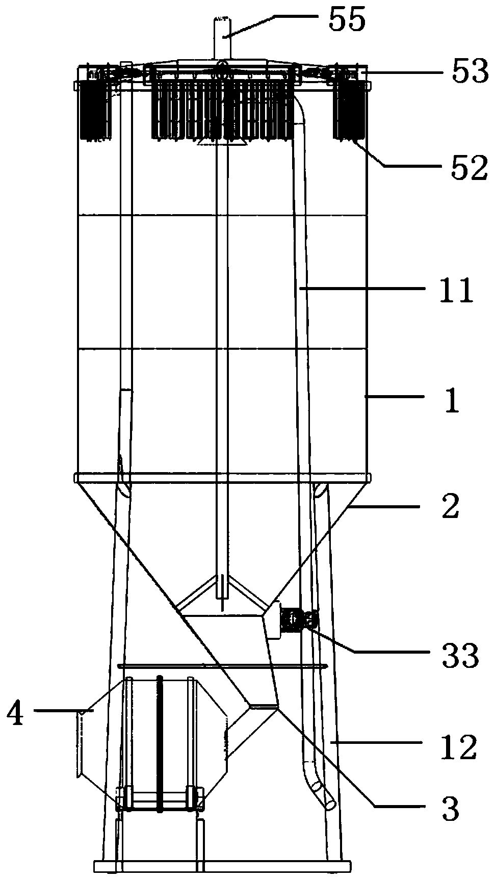
[0036] Such as Figure 1-Figure 3 As shown, a mortar tank with automatic dust collection function includes a tank body 1, a feed pipe 11 extending into the inside of the tank body 1, and a support frame composed of four supporting legs 12 arranged under the tank body 1. The tank body 1. The lower part is a cone part 2, and the bottom of the tank is provided with a discharge port 3, which communicates with the mixer 4.

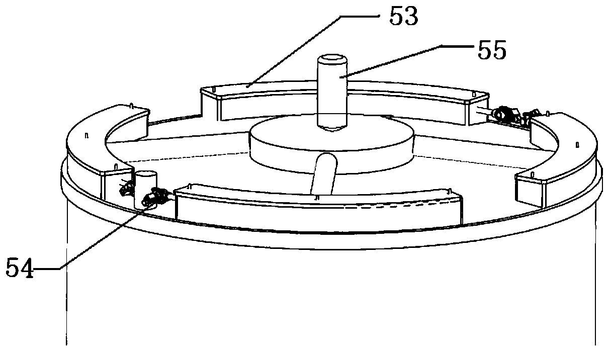
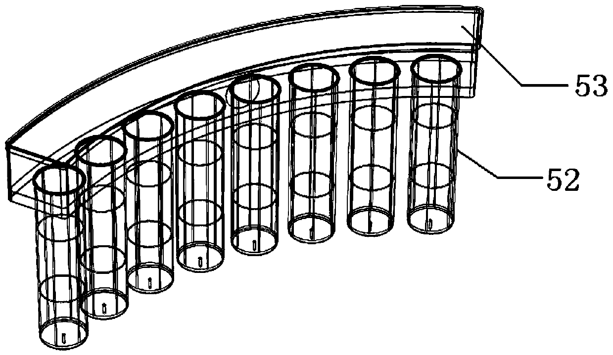
[0037] The top of the tank body 1 is provided with a ventilation opening 55, and the four dust removal boxes 53 communicate with the ventilation openings 55 through pipes, and each dust removal box 53 is provided with several dust removal filter bags 52. Also be provided with the dedusting nozzle of the second electromagnetic pulse valve 54 in each dedusting box 53, the air inlet pipe of dedusting nozzle is the support leg 12 of hollow, totally 4 support legs, and support leg 12 is interconnected by hollow pipe, unified As an air storage chamber for compressed...

Embodiment 2

[0044] As a description of Embodiment 2 of the present invention, only the differences from Embodiment 1 above will be described below.

[0045] Such as Figure 4 As shown, the cone part 2 of the mortar tank is also provided with four air nozzles 32 facing the conical inner wall, each air nozzle 32 is provided with a first electromagnetic pulse valve 31, and each supporting leg 12 is correspondingly provided with an air nozzle 32. The air nozzles 32 are evenly distributed along the radial direction of the cone. Air compressed by the air compressor 33 is stored in the support leg 12 to supply air to the air nozzle 32 .

[0046] The discharge port 3 is provided with a butterfly valve with a position detection switch, the position detection switch is connected to a solenoid valve controller, and the solenoid valve controller drives the first electromagnetic pulse valve 31 to control the opening and closing of the air nozzle 32 .

[0047] In this embodiment, there are 4 support ...

Embodiment 3

[0054] As an explanation of Embodiment 3 of the present invention, only the differences from Embodiment 1 above will be described below.

[0055] In this embodiment, on the basis of Embodiment 1, the dust suction pipe 6 and the dust removal fan 51 are added. Such as Figure 5 As shown, one end of the ash suction pipe 6 extends into the tank body of the mixer, the opening is located near the dustproof filter bag 52 , and the opening at the other end is located at the entrance of the mixer 4 . The part of the ash suction pipe 6 in the tank body is a metal hard tube, and the part extending out of the tank body is a plastic tube.

[0056] Such as Figure 6 As shown, the vent 55 at the top of the tank body is equipped with a dust removal fan 51, and the four dust removal boxes are connected with the dust removal fan 51 after being collected through pipelines.

[0057] The structure of the mortar mixer adopts the way of front and rear through holes to enter the feeding and discha...


PUM


Abstract

The invention discloses a mortar tank with an automatic dust-collecting function. The mortar tank with the automatic dust-collecting function comprises a tank body, a feeding pipe and a supporting rack. The feeding pipe extends into the tank body, the supporting rack is arranged on the lower part of the tank body, the lower part of the tank body is a tapered part, a discharging port is formed on the bottom of the mortar tank, and the discharging port communicates with a blending machine; a plurality of dust-removing filtering bags are arranged at the position, close to the top, of the tank body, and the dust-removing filtering bags are gathered through one or more dust-removing tanks and communicate with an air vent arranged at the top of the tank body. According to the mortar tank with the automatic dust-collecting function, when mortar materials are conveyed to the mortar tank by mortar through the feeding pipe, in the action of the dust-removing filtering bags, powder can be blockedin the tank body, and thus air pollution is avoided.

Description

technical field [0001] The invention belongs to the field of mortar mechanical equipment, in particular to a mortar tank with automatic dust collection function. Background technique [0002] In recent years, with the restrictions on mixing bagged mortar on site at construction sites, filling mortar has been widely used in construction and municipal construction projects, and various mortar tanks have also emerged as the times require. [0003] As the last link of mortar production, transportation, and storage, mortar tanks have two major industry problems: dust collection when mortar is sent into the tank, and unloading and segregation when using mortar. In order to facilitate the transportation, storage and use of mortar tanks, the tank body is often designed as a cylinder, and the bottom of the tank is designed as an inverted cone at about 50 degrees to reduce the discharge port and facilitate the control of the discharge volume. The mortar is pumped into the tank throug...

Claims


Application Information

Patent Timeline
Patent Type & Authority Applications(China)
IPC IPC(8): B28C7/00
CPCB28C7/0007B28C7/0053B28C7/0076
Inventor 来敏陈胡星
Owner ZHEJIANG UNIV
Why Eureka
Try Eureka