Crane hook 90° positioning anti-rotation device

A crane and hook technology, applied in the field of lifting equipment, can solve the problems of high use cost, inconvenient operation, economic loss, etc., and achieve the effects of reducing outsourcing cost, compact structure and high cost performance

Active Publication Date: 2016-07-20
SHANGHAI BAOSONG YANCHENG HEAVY MACHINERY ENG
View PDF8 Cites 0 Cited by
  • Summary
  • Abstract
  • Description
  • Claims
  • Application Information

AI Technical Summary

Problems solved by technology

[0002] There are two types of hook sets for cranes: the traditional type and the anchor hook type. When the traditional type of hook set is lifting heavy objects, due to the deviation of the center of gravity of the heavy objects or the inclination of the wire rope, the hooks often cause the hook The hook head and the heavy object are constantly swinging or rotating for a long time, which is prone to bumping and causing unnecessary economic losses, especially when lifting special items such as high temperature and easy corrosion, there is still a relatively large safety hazard; and Although the anchor hook type hook group does not have the above problems, it has high requirements for the placement of the lifting objects and is inconvenient to operate; Put the pin to achieve the 90° mechanical positioning anti-rotation of the hook group; although this technology overcomes the existing problems, the price of this 90° mechanical positioning anti-rotation hook group is much higher than that of its full-angle rotation hook group. high cost

Method used


Image

  • Crane hook 90° positioning anti-rotation device
  • Crane hook 90° positioning anti-rotation device
  • Crane hook 90° positioning anti-rotation device

Examples


Embodiment Construction

[0024] In order to further illustrate the above-mentioned purpose, technical scheme and effect of the present invention, the present invention will be described below in conjunction with the accompanying drawings and relevant known technical knowledge through the embodiments:

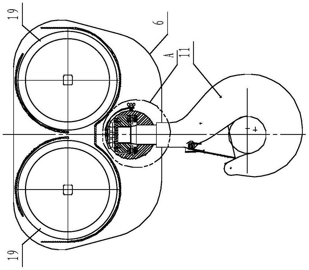
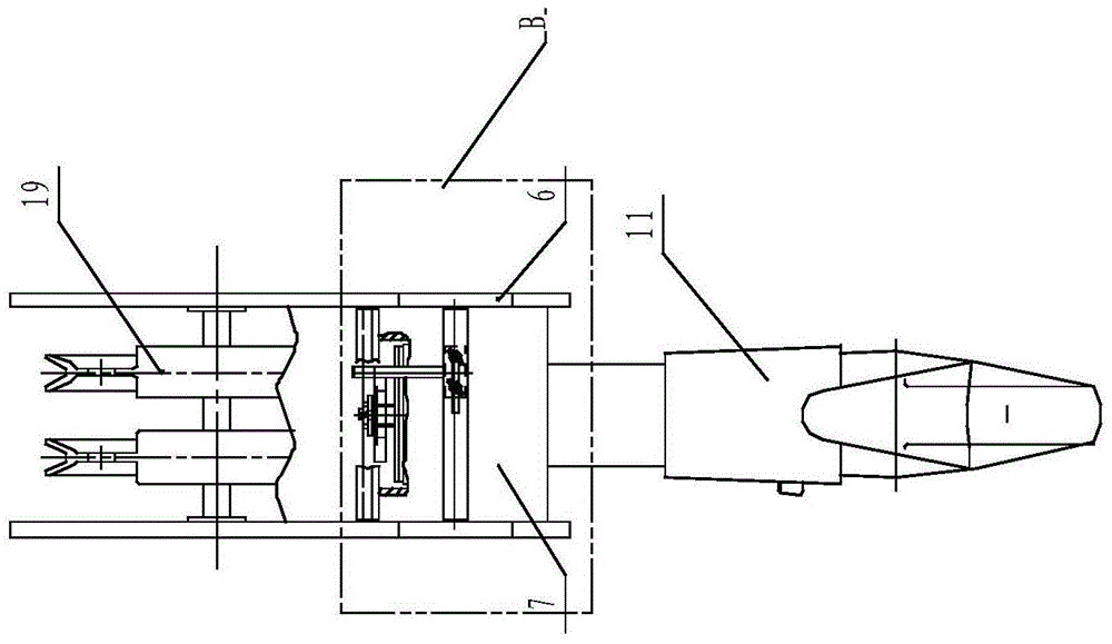
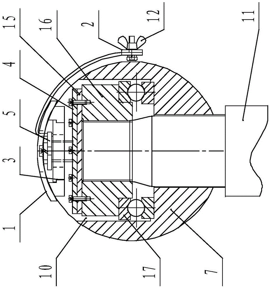
[0025] Such as Figure 1-3 As shown, the crane hook 90° positioning anti-rotation device includes a pulley block 19, two parallel hoisting yoke plates 6 and a hook block, and the pulley block 19 and the hook block located at the lower side of the pulley block 19 are arranged on two blocks. Between the hoisting yoke plates 6 arranged in parallel, the pulley block 19 is supported on the upper part of the two hoisting yoke plates 6 through a transverse shaft; The end lock plate 15, the upper end of the hook body 11 vertically penetrates into the hole set in the middle of the crossbeam 7, and after matching with the center hole of the thrust ball bearing 17, the screw at the upper end of the hook body 11 is...


PUM


Abstract

The invention relates to a hook 90-DEG location rotation-preventing device for a crane. The hook 90-DEG location rotation-preventing device is characterized in that no hook 90-DEG location rotation-preventing device is arranged on a shaft end locking plate in the middle of a cross beam; the hook 90-DEG location rotation-preventing device comprises a stop plate, a location plate, a sliding fixed plate, a base plate and a pressing plate, wherein the base plate is fixed on the shaft end locking plate, the sliding fixed plate is an assembly after a guide rail and the stop plate are matched, and is arranged on the cross beam between two hoisting yoke plates, a square shaft on the base plate penetrates through a round hole in the sliding fixed plate, and then the pressing plate is fixed on the base plate, the sliding fixed plate and the location plate are connected together, and then are locked by moving a square or round location hole of the sliding fixed plate so that a hook group rotates for 360 DEG or 90 DEG to be mechanically located. The hook 90-DEG location rotation-preventing device is compact and simple in structure, high in performance cost ratio, and convenient to use; the original use performance of a hook group is not influenced after the hook group is installed, the hook group is not dismantled and reconstructed when being installed, and thus the hook 90-DEG location rotation-preventing device has a popularization and use value.

Description

technical field [0001] The invention relates to a crane hook, in particular to a 90° positioning and anti-rotation device for a crane hook, belonging to the technical field of lifting equipment. Background technique [0002] There are two types of hook sets for cranes: the traditional type and the anchor hook type. When the traditional type of hook set lifts heavy objects, due to the deviation of the center of gravity of the heavy objects or the inclination of the steel wire rope, the hooks are often caused when the object is lifted off the ground. The hook head and the heavy object swing or rotate continuously for a long time, which is prone to bumping and causing unnecessary economic losses, especially when lifting special items such as high temperature and easy corrosion, there is still a relatively large safety hazard; and Although the anchor hook type hook group does not have the above problems, it has high requirements for the placement of the lifting items and is inco...

Claims


Application Information

Patent Timeline
Patent Type & Authority Patents(China)
IPC IPC(8): B66C1/34B66C13/06
Inventor 孙文明
Owner SHANGHAI BAOSONG YANCHENG HEAVY MACHINERY ENG
Why Eureka
Try Eureka