Surface acoustic wave electric current sensor

A technology of current sensor and surface acoustic wave, which is applied in the direction of measuring current/voltage, instruments, and measuring electrical variables, etc. It can solve the problems of large energy loss of reflectors, low signal-to-noise ratio of reflected signals, and huge influence on the stability of current sensors. Achieve good temperature stability and high detection sensitivity

Inactive Publication Date: 2014-07-30
INST OF ACOUSTICS CHINESE ACAD OF SCI +1
View PDF3 Cites 21 Cited by
  • Summary
  • Abstract
  • Description
  • Claims
  • Application Information

AI Technical Summary

Benefits of technology

The inventors developed an improved type called radioactive SAW (acoustic wave) flow meter that can accurately measure electricity flows at very low voltages while also being able to withstand temperatures up to 100 degrees Celsius. This technology allows for better monitoring of these types of conditions without having to be installed permanently or requiring expensive equipment.

Problems solved by technology

Technological Problem addressed in this patented technical problem relating to the limitations associated with traditional SAW type detectors used in electronic currents applications include instability over varying temperatures during operation, reduced efficiency or sensibility resolution, limited usages in different environmental situations, difficulty in manufacturing large quantities of these types of components, and potential issues like low reliabilities in long term measurements.

Method used


Image

  • Surface acoustic wave electric current sensor
  • Surface acoustic wave electric current sensor
  • Surface acoustic wave electric current sensor

Examples


Embodiment Construction

[0044] The technical solutions of the present invention will be described in further detail below with reference to the accompanying drawings and embodiments.

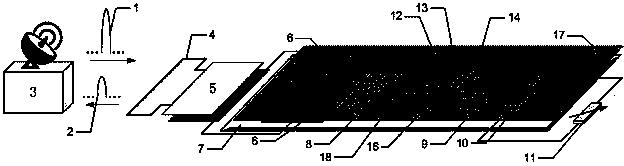
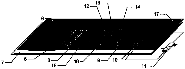
[0045] Figure 2a A schematic diagram of the composition of the SAW current sensor provided by the embodiment of the present invention, such as Figure 2a As shown, the SAW current sensor includes: a first electromagnetic wave signal 1, a second electromagnetic wave signal 2, a reading unit 3, a wireless antenna 4, an impedance matching network 5, a conductive film 6, a piezoelectric substrate 7, EWC / SPUDT8, the second One-way reflector (comprising: first interdigital reflector 9 and second interdigital reflector 10), magnetoresistor 11, second-way reflector (comprising: first short-circuit grid reflector 12, second short-circuit grid reflector 13 and the third short grid reflector 14), the first sound-absorbing glue 15, the second sound-absorbing glue 15', the echo signal 16 of the first road reflector, thin film 17,...


PUM

PropertyMeasurementUnit
Electron mobilityaaaaaaaaaa
Resistivityaaaaaaaaaa

Abstract

The invention relates to a surface acoustic wave (SAW) electric current sensor which comprises a piezoelectric substrate, a first line of reflectors, a second line of reflectors and a thin film layer. The piezoelectric substrate serves as a vibrating membrane, the first line of reflectors comprise the first interdigital reflector serving as a reference and the second interdigital reflector used for measuring electric currents, the second line of reflectors serve as electronic tags, and the first line of reflectors and the second line of reflectors are coated with the thin film layer. First electromagnetic wave signals sent by a reading module are received through a wireless antenna, the first electromagnetic wave signals are converted into SAWs spread along the surface of the piezoelectric substrate through an EWC/SPUDT, the SAWs are converted into second electromagnetic wave signals through the EWC/SPUDT after being reflected by the first line of reflectors and the second line of reflectors, the second electromagnetic wave signals are transmitted back to the reading unit through the wireless antenna, through a signal processing method, the current detection is carried out by obtaining the signal transformation of the time-domain response of the SAW electric current transducer.

Description


Claims


Application Information

Patent Timeline
Owner INST OF ACOUSTICS CHINESE ACAD OF SCI
Why Eureka
Try Eureka