Substrate bonding process and substrate components to be bonded

A technology for bonding substrates and substrates, applied in optics, instruments, nonlinear optics, etc., can solve the problems of corroding circuit metal wires, loss, acid liquid entry, etc.

Inactive Publication Date: 2017-04-05
BOE TECH GRP CO LTD +1
View PDF5 Cites 0 Cited by
  • Summary
  • Abstract
  • Description
  • Claims
  • Application Information

AI Technical Summary

Problems solved by technology

However, the disadvantage of this approach is that the opening of the peripheral plastic frame will cause acid liquid to enter between the box plastic frame and the peripheral plastic frame during the subsequent thinning process, corroding the circuit metal wires and component switches, causing unnecessary losses

Method used


Image

  • Substrate bonding process and substrate components to be bonded
  • Substrate bonding process and substrate components to be bonded
  • Substrate bonding process and substrate components to be bonded

Examples


Embodiment 1

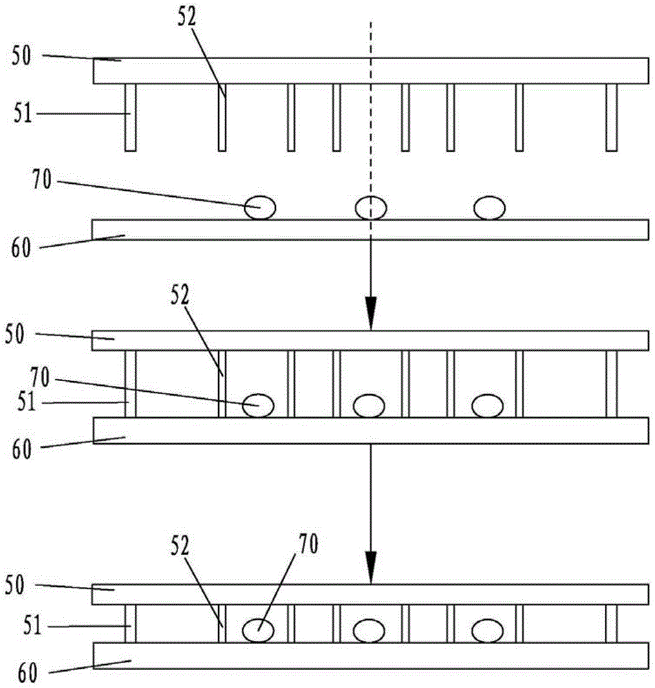
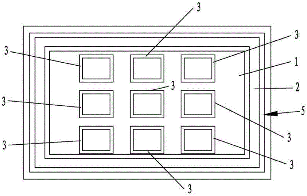
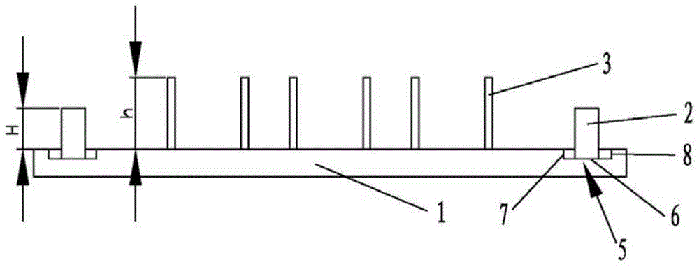
[0075] Such as Figure 5 As shown, Embodiment 1 of the substrate bonding process for forming a liquid crystal panel of the present invention includes:

[0076] A peripheral plastic frame 20 is arranged on the surface of the first substrate 10, and a box-shaped plastic frame 30 for sealing liquid crystals is arranged inside the peripheral plastic frame 20. The height of the box-shaped plastic frame 30 is greater than the height of the peripheral plastic frame 20;

[0077] The first substrate 10 is opposite to the second substrate 100, and the side of the first substrate 10 provided with the peripheral plastic frame 20 and the box-forming plastic frame 30 is opposite to the second substrate 100;

[0078] removing the gas between the first substrate 10 and the second substrate 100;

[0079] The first substrate 10 and the second substrate 100 are preliminarily bonded, the box-forming plastic frame 30 is in contact with the second substrate 100, and there is a gap between the peri...

Embodiment 2

[0087] Such as Image 6 As shown, Embodiment 2 of the substrate bonding process for forming a liquid crystal panel of the present invention includes:

[0088] In the middle part of the surface of the first substrate 10', a box-forming plastic frame 30' for sealing liquid crystals is arranged, and a peripheral plastic frame 20' is arranged on the edge of the surface of the second substrate 100', and the height of the box-forming plastic frame 30' is greater than that of the periphery The height of the plastic frame is 20';

[0089] Make the first substrate 10' and the second substrate 100' opposite, the side of the first substrate 10' that is provided with the box plastic frame 30' is opposite to the side that is provided with the peripheral plastic frame 20' of the second substrate 100';

[0090] Excluding the gas between the first substrate 10' and the second substrate 100';

[0091] The first substrate 10' and the second substrate 100' are preliminarily bonded, the box-for...


PUM

PropertyMeasurementUnit
heightaaaaaaaaaa
heightaaaaaaaaaa
depthaaaaaaaaaa

Abstract

The present invention provides a substrate fitting process and a substrate assembly to be fitted, wherein the substrate assembly to be fitted of the present invention, a periphery mold frame is disposed on a surface of a substrate, a cell mold frame is disposed inside said periphery mold frame, the height of said cell mold frame is larger than the height of said periphery mold frame. A substrate fitting process of the present invention comprises: providing a cell mold frame on a surface of a first substrate, providing a cell mold frame inside the periphery mold frame for sealing liquid crystal, the height of said cell mold frame is larger than the height of the periphery mold frame; extracting the air between the first substrate and the second substrate; making the first substrate fit with the second substrate preliminarily; filling the air between the first substrate and the second substrate; making the first substrate further fit with the second substrate. With the technical solution of the present invention, the puncture caused by the impact of the in-cell liquid crystal onto the cell mold frame is prevented, and the time and the costs of the process is decreased, meanwhile the probability of the circuit metal wire and the component switch on the liquid crystal panel suffering corrode of the thinning acid is decreased.

Description

technical field [0001] The invention relates to the field of display technology, in particular to a substrate bonding process and a substrate component to be bonded. Background technique [0002] In the manufacturing process of the existing liquid crystal display panel, the array substrate (TFT) and the color filter substrate (CF) need to be bonded together by a sealing glue. According to the different coating positions of the sealant, the sealant is divided into the main sealant for sealing the liquid crystal in the box and the peripheral sealant for maintaining the stability of the gap between the substrates. Such as figure 1 As shown, in the substrate bonding process of the prior art, the peripheral rubber frame 51 formed by the peripheral sealant of the substrate is usually arranged on the surface of the first substrate 50, and the box formed by the main sealant is arranged inside the peripheral rubber frame 51. Plastic frame 52; make the first substrate 51 and the sec...

Claims


Application Information

Patent Timeline
Patent Type & Authority Patents(China)
IPC IPC(8): G02F1/1333G02F1/1339
CPCB32B3/02B32B3/085B32B2307/558B32B2307/714B32B2457/202G02F1/1339G02F1/133354G02F1/133388
Inventor 肖昂宋省勋陈旭
Owner BOE TECH GRP CO LTD
Why Eureka
Try Eureka