Fuel cell structure with self-humidifying function

A fuel cell and fuel cell unit technology, applied in the direction of fuel cells, fuel cell additives, fuel cell grouping, etc., can solve the problems of increasing the size and weight of fuel cells

Active Publication Date: 2014-07-30
SHANGHAI INST OF SPACE POWER SOURCES
View PDF3 Cites 6 Cited by
  • Summary
  • Abstract
  • Description
  • Claims
  • Application Information

AI Technical Summary

Problems solved by technology

However, both external humidification and internal humidification increase the size and weight of the fuel cell

Method used


Image

  • Fuel cell structure with self-humidifying function
  • Fuel cell structure with self-humidifying function
  • Fuel cell structure with self-humidifying function

Examples


Embodiment 1

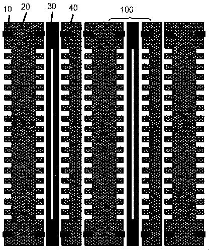
[0033] A conventional complete single fuel cell includes a sealing ring 10, a water oxygen plate 20, a membrane electrode 30 and a single hydrogen plate 40, such as figure 1 shown.

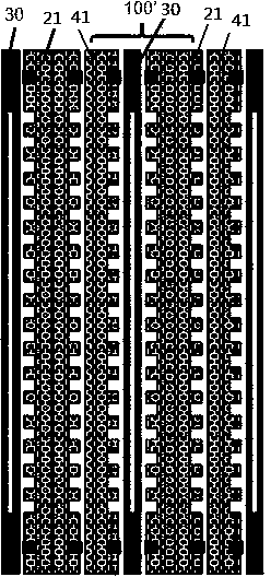
[0034] In this example, if figure 2 As shown, a microporous plate fuel cell structure with hydrogen side and oxygen side self-humidification function is provided, and the cell structure includes several fuel cell units connected in series, wherein each complete single fuel cell includes:

[0035] Sealing rings 10 placed at both ends of the fuel cell unit;

[0036] a membrane electrode 30 disposed in the middle of the fuel cell unit; and

[0037] The microporous water-oxygen humidification pole plate 21 and the microporous monohydrogen humidification pole plate 41 are respectively arranged on both sides of the membrane electrode 30 .

[0038] Fuel cell humidification water comes from cooling water with a temperature of 75°C to 80°C. The humidifying water passes through the cooling water fl...

Embodiment 2

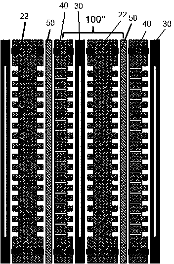
[0041] Such as image 3 As shown, another kind of porous plate fuel cell structure with oxygen side self-humidification function provided by the present invention, this cell structure includes several fuel cell units connected in series, wherein each complete single fuel cell includes:

[0042] Sealing rings 10 placed at both ends of the fuel cell unit;

[0043] Membrane electrode 30 arranged in the middle of the fuel cell unit;

[0044] The hydrogen pole plate and the oxygen pole plate with self-humidification structure are respectively arranged on both sides of the membrane electrode 30 .

[0045] The oxygen plate with self-humidification structure is a combination of porous single oxygen humidification plate 22 and membrane 50, and the porous single oxygen humidification plate 22 is located between the membrane electrode 30 and the membrane 50; Plate 40, membrane electrode 30, porous single-oxygen humidification plate 22 and membrane 50 are assembled in sequence to form a...

Embodiment 3

[0050] Such as Figure 4 As shown, a porous plate fuel cell structure with hydrogen side and oxygen side self-humidification function is provided. Water plate 60; wherein each complete single fuel cell comprises:

[0051] Seal rings 10 placed at both ends of the fuel cell unit;

[0052] Membrane electrode 30 arranged in the middle of the fuel cell unit;

[0053] An oxygen plate with a self-humidification structure and a hydrogen plate with a self-humidification structure respectively arranged on both sides of the membrane electrode 30;

[0054] Wherein, the oxygen pole plate is a combination of porous single oxygen humidification pole plate 22 and membrane 50; the hydrogen pole plate is a combination of porous single hydrogen humidification pole plate 42 and membrane 50; in the battery structure, according to the membrane 50. A single cell is assembled in sequence of the porous single oxygen humidification pole plate 22, the membrane electrode 30, the porous single hydrogen...


PUM


Abstract

The invention discloses a fuel cell structure with a self-humidifying function. The fuel cell structure comprises a plurality of fuel cell units, wherein each fuel cell unit comprises sealing rings arranged at two ends of the fuel cell unit, a membrane electrode arranged in the middle of the fuel cell unit, and an oxygen polar plate and a hydrogen polar plate which are respectively arranged on two sides of the membrane electrode; at least one of the hydrogen polar plate and the oxygen polar plate has a self-humidifying structure, and a micropore polar plate or combination of a porous polar plate and a membrane is selected as the self-humidifying structure, so that a gas-blocking and water-permeating function is achieved. According to the fuel cell structure disclosed by the invention, water from a middle cooling water plate permeates through a water-permeating and gas-blocking membrane or micropore for humidifying the polar plates so that the membrane electrode of the fuel battery is humidified, an external humidifying device is prevented from being used, system assemblies are reduced, system weight is lightened, and system energy consumption caused by the humidifying device is reduced.

Description

technical field [0001] The invention relates to the field of fuel cell preparation, in particular to a fuel cell structure with self-humidification function. Background technique [0002] In the fuel cell system spacecraft application, the electric drive moving parts in the pure hydrogen and pure oxygen system not only increase the parasitic energy consumption, extra weight and complexity of the system, but also greatly reduce the reliability of the system, and even cause catastrophic accidents ; Active circulating liquid cooling and other auxiliary systems in the system are heavy, which also brings about problems such as high parasitic energy consumption and low reliability. Simplifying the system structure and reducing the auxiliary energy consumption of the system are one of the main directions for the development of fuel cells. [0003] At present, the main direction to simplify the fuel cell system is to simplify the humidification system. The humidification method of...

Claims


Application Information

Patent Timeline
Patent Type & Authority Applications(China)
IPC IPC(8): H01M8/24H01M8/04H01M4/86H01M8/04828
CPCH01M8/04126Y02E60/50
Inventor 孙毅张建琴张伟刘向朱荣杰蒋永伟张新荣
Owner SHANGHAI INST OF SPACE POWER SOURCES
Why Eureka
Try Eureka