
A Dielectric Filter with Low Air Pressure and High Power Threshold

A dielectric filter and high-power technology, applied in waveguide devices, electrical components, circuits, etc., can solve the problems of dielectric filter power threshold reduction, thin cover plate deformation cannot be recovered, and stress cannot be released quickly, so as to achieve low The effect of air pressure power threshold, increased fatigue resistance and service life, and reduced maximum electric field value and voltage value

Active Publication Date: 2016-02-10
XIAN INSTITUE OF SPACE RADIO TECH
View PDF3 Cites 0 Cited by
  • Summary
  • Abstract
  • Description
  • Claims
  • Application Information

AI Technical Summary

Problems solved by technology

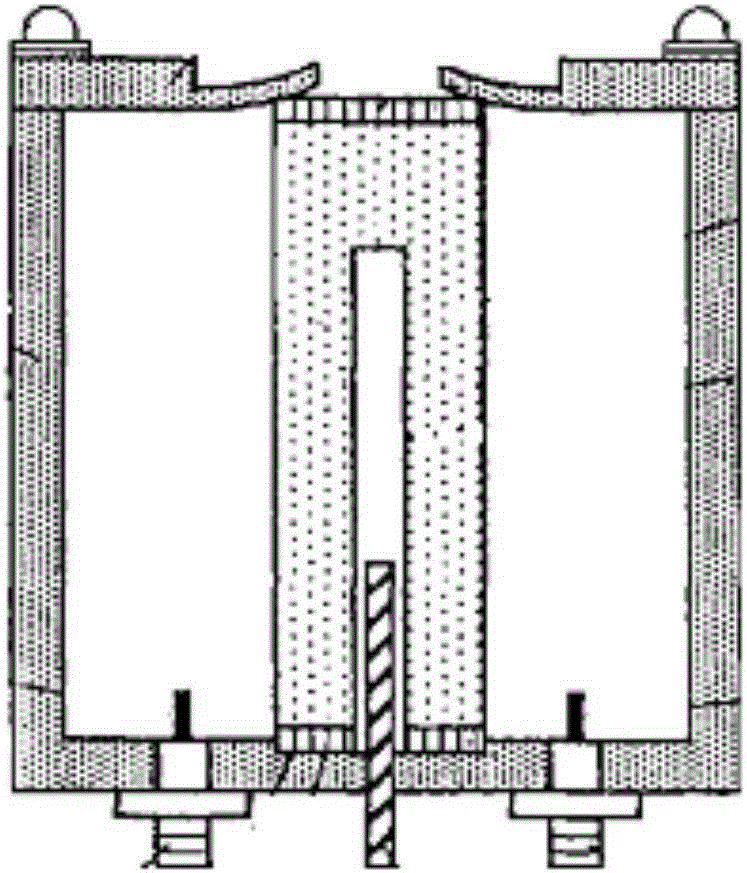
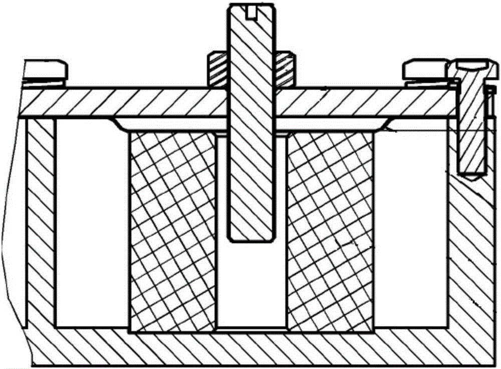
However, the existing dielectric filter structure at home and abroad cannot fully meet the reliability and completeness required by the spaceborne filter, such as the deformation structure of the cover plate ( figure 1 ) and double-layer cover structure ( figure 2 ) cannot meet the requirements under different mechanical, temperature environments and vacuum conditions: the former due to the stress in the satellite fatigue endurance test, the deformation of the thin cover plate cannot be recovered eventually, resulting in the failure of the filter performance; the latter in the mechanical shock vibration test The resulting stress cannot be released quickly, resulting in changes in filter performance
In addition, the traditional dielectric filter adopts the structure of a limit table or a metal frequency adjustment screw, which disturbs the electromagnetic field in the cavity of the dielectric resonator too much, so that the power threshold of the dielectric filter is rapidly reduced.

Method used


Image

  • A Dielectric Filter with Low Air Pressure and High Power Threshold
  • A Dielectric Filter with Low Air Pressure and High Power Threshold
  • A Dielectric Filter with Low Air Pressure and High Power Threshold

Examples


Embodiment Construction

[0030] Specific embodiments of the present invention will be further described in detail below in conjunction with the accompanying drawings.

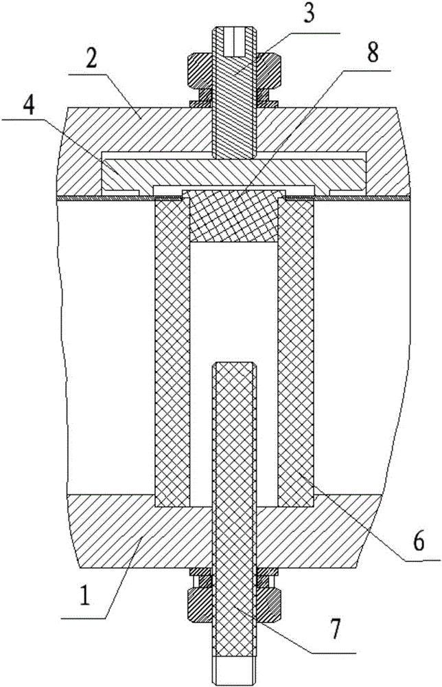
[0031] like image 3 As shown, a low-pressure high-power threshold dielectric filter of the present invention includes: a pressure adjustment mechanism, a cavity 1, a dielectric resonator 6, a frequency tuning screw 7, a positioning dielectric block 8, a welding rod 9, a joint 10, a tight Fixing screw 11; the pressure adjustment structure includes an upper cover plate 2, a pressing force adjustment screw 3, a metal pressure block 4, and a thin cover plate 5;

[0032] There is a counterbore on the bottom surface of the upper cover plate 2, the metal pressure block 4 is located under the counterbore hole of the upper cover plate 2, the metal pressure block 4 and the upper cover plate 2 are located on the upper surface of the thin cover plate 5, and one end of the pressing force adjustment screw 3 Through the upper cover plate 2 and agai...


PUM


Abstract

A dielectric filter with a low-pressure high-power threshold value comprises a filter cavity, an upper cover board, a pressing force adjusting screw, a metal pressing block, a thin cover board, a dielectric resonator, a frequency tuning screw, a locating dielectric block, a welding rod, a connector and a fastening screw. The adjusting structure of the pressing force adjusting screw, the upper cover board, the metal pressing block and the thin cover board is designed, the dielectric resonator is placed between a cavity limiting pit and the thin cover board, the dielectric resonator, the thin cover board and the cavity make good contact in different temperature, mechanics and vacuum environments through adjustment of a pressure tuning screw, and it is guaranteed that the working performance of the TM01 mode dielectric filter is reliable and stable in different environments. The mode that the locating dielectric block and a dielectric tuning screw are combined is adopted, an electromagnetic field in the dielectric resonator is slightly disturbed, and compared with a tuning screw made of metal, the low-pressure power threshold value of the filter is obviously increased.

Description

technical field [0001] The invention relates to a low-pressure high-power threshold dielectric filter, which belongs to the field of ground and satellite communication microwave device design. Background technique [0002] my country's application of satellite technology is developing rapidly: on the one hand, in order to improve communication transmission performance, the working power of space-borne microwave equipment is required to be higher and higher; on the other hand, in order to improve integration, the volume and weight of space-borne microwave equipment are required to be smaller and smaller . Two aspects lead to the appearance of uneven and high-intensity electric field in the spaceborne microwave equipment, which will cause the discharge effect. Coaxial filters are widely used in satellite forwarding, measurement and control, and remote sensing systems. In order to obtain a higher power threshold, it is necessary to increase the volume and weight. [0003] In m...

Claims


Application Information

Patent Timeline
Patent Type & Authority Patents(China)
IPC IPC(8): H01P1/20H01P1/208
Inventor 李亚峰林浩佳袁建荣李吉斌殷新社
Owner XIAN INSTITUE OF SPACE RADIO TECH
Learn More