An energy-saving and environment-friendly mechanical energy battery
An energy-saving, environmentally friendly, mechanical energy technology, applied in the direction of electromechanical devices, electrical components, etc., to achieve the effect of simple battery structure
- Summary
- Abstract
- Description
- Claims
- Application Information
AI Technical Summary
Problems solved by technology
Method used
Image

Examples
Embodiment Construction
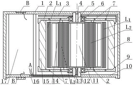
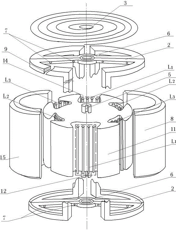
[0011] exist figure 1 Among them, the silicon steel laminated iron core (11) is fixed on the fixed shaft (12) with lead slots (5) at both ends, and the first coil (L 1 ), the second coil (L 2 ), the third coil (L 3 ) symmetrically and tightly wound in the corresponding slots (14) on the laminated silicon steel core (11) to form the stator of the generator. On the shaft (12), the inner end of the worm spring (3) is fixed on the fixed shaft (12), and the outer end is fixed on the edge of the magnet bracket (2). The first arc-shaped permanent magnet (8) with an outer slope on the top and the second arc-shaped permanent magnet (15) with an outer slope on the top are correspondingly fixed on both sides of the magnet bracket (2), and the first top has an outer slope The polarity of the arc-shaped permanent magnet (8) and the second arc-shaped permanent magnet (15) with an outer slope on the top are opposite, and the quality is different. The magnet bracket (2) is screwed togethe...
PUM
 Abstract
Description
Claims
Application Information
 - R&D
- Intellectual Property
- Life Sciences
- Materials
- Tech Scout
- Unparalleled Data Quality
- Higher Quality Content
- 60% Fewer Hallucinations
Browse by: Latest US Patents, China's latest patents, Technical Efficacy Thesaurus, Application Domain, Technology Topic, Popular Technical Reports.
© 2025 PatSnap. All rights reserved.Legal|Privacy policy|Modern Slavery Act Transparency Statement|Sitemap|About US| Contact US: help@patsnap.com