
A Spiral Nozzle Applicable to Wet Electrostatic Precipitator and Its Arrangement

A wet electrostatic precipitator and spiral technology, used in electrostatic separation, electrode cleaning, etc., can solve the overlapping of spray distribution, the nozzle setting spacing, the surface of the dust collecting electrode cannot be completely covered by the spray liquid, and the spray is uneven, etc. problems, to achieve the effect of saving investment and operating costs, good cleaning and dust removal, and reducing the number of nozzles

Active Publication Date: 2016-05-25
SHANGHAI LONGKING ENVIRONMENTAL PROTECTION
View PDF7 Cites 0 Cited by
  • Summary
  • Abstract
  • Description
  • Claims
  • Application Information

AI Technical Summary

Problems solved by technology

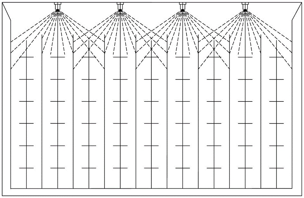
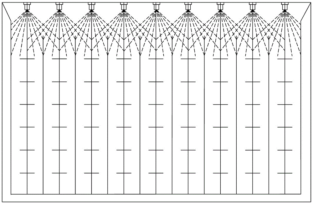
The arrangement position of the nozzles in the prior art also often has the following problems: the distance between the nozzles is too large (twice or more than twice the dust collection channel), which will easily cause the surface of some dust collection poles to not be completely covered by the spray liquid, resulting in Spray "dead angle", unable to form a complete smooth water film (see figure 2 , the nozzle spacing is too large); if the number of nozzles increases, the nozzle spacing is less than twice the dust collection channel, although it can avoid the appearance of "dead angles" in spraying, but it is easy to overlap the spraying range and spray unevenly (see image 3 , the nozzle spacing is too small), resulting in increased water consumption and increased operating costs

Method used


Image

  • A Spiral Nozzle Applicable to Wet Electrostatic Precipitator and Its Arrangement
  • A Spiral Nozzle Applicable to Wet Electrostatic Precipitator and Its Arrangement
  • A Spiral Nozzle Applicable to Wet Electrostatic Precipitator and Its Arrangement

Examples


Embodiment 1

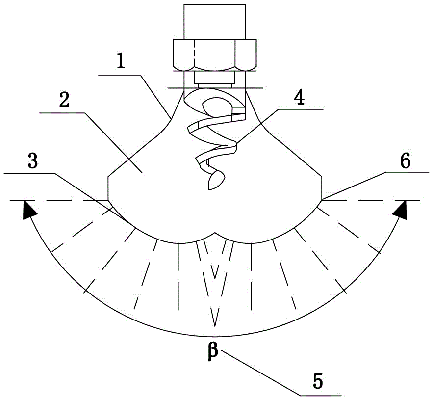
[0026] figure 1 It is a structural schematic diagram of the spiral nozzle suitable for the wet electrostatic precipitator proposed by the present invention. Such as figure 1 As shown, the structure of the spiral nozzle includes a spiral nozzle 4 and a spray housing 2, the spiral nozzle 4 is placed in the inner cavity of the spray housing 2, and the bottom of the spray housing 2 is a spray surface 3, which is convex and symmetrical Double spherical structure, the surface is uniformly arranged with a plurality of spray holes perpendicular to the radial direction of the spherical surface of the spray surface 3, from figure 1 It can be seen that the spray angle β5 can reach up to 180°.

[0027] figure 1 The spray mode of the spiral nozzle 1 can be set as an intermittent mode or a continuous mode.

Embodiment 2

[0029] The spiral nozzle 1 of the present invention is used in wet electrostatic precipitators as a dust collector cleaning device for flat, tubular or honeycomb wet electrostatic precipitators, or as a cleaning device for corona electrodes of wet electrostatic precipitators.

[0030] figure 2 with image 3 It is a schematic diagram of the two arrangement positions of the existing common nozzles in the plate structure wet electrostatic precipitator. When the installation arrangement distance of common nozzles is too large, which is equal to (or greater than) two dust collection channels 10 (a dust collection channel is formed between two rows of dust collection electrodes), such as figure 2 As shown, it is easy to cause the surface of some dust collectors to be unable to be completely covered by the spray liquid, and there will be a spray "dead angle", and a complete and smooth water film cannot be formed; if the arrangement distance of ordinary nozzles is reduced, such as ...

Embodiment 3

[0034] The arrangement positions of the spiral nozzle 1 proposed by the present invention in the honeycomb structure wet electrostatic precipitator (taking the rhombus structure as an example) are as follows Figure 5 , 6 , 7, 8 shown.

[0035] Figure 5 Shown is a schematic diagram of the arrangement position of the spiral nozzle 1 in a diamond-shaped structure (a kind of honeycomb) wet electrostatic precipitator, which is represented by Figure 5 It can be seen that the spiral nozzles 1 are arranged above the common corner of the rhombus-shaped dust collection pole 7, and the cross-sectional schematic diagram of the spray distribution range of this arrangement is as follows: Image 6 shown, from Image 6 It can be seen that each dust collecting pole can be covered by spraying.

[0036] Figure 7 It is a schematic diagram of another arrangement position of the spiral nozzle 1 in the diamond-shaped wet electrostatic precipitator, that is, the spiral nozzle 1 is placed abo...


PUM


Abstract

The invention provides a spiral spray nozzle applicable to a wet electric precipitator and an arrangement way of the spiral spray nozzle, aims to solve the technical problems of ultrafine atomization effect achievement, optimal arrangement of the spray nozzle and improvement on the dust-removing efficiency, and belongs to the technical field of smoke gas treatment. The spiral spray nozzle is characterized by comprising a spiral spray head and a spraying shell, wherein the spiral spray head is arranged in the inner cavity of the spraying shell; the bottom of the spraying shell is a spraying surface which adopts an outwards-convex symmetric double-spherical surface structure; a plurality of spray holes which are perpendicular to the spherical surfaces of the spraying surface in the radial direction are uniformly formed; the spraying angle beta is less than or equal to 180 degrees. The spiral spray nozzle provided by the invention is applicable to the wet electric precipitator; spraying particles are tiny and uniform and the spraying angle and the spraying range are large, so that the flushing effect of the dust collecting electrode of the wet electrostatic precipitator can be effectively improved, the number of the spray nozzles can be reduced, the water consumption can be effectively reduced, wear of the spray nozzle can be avoided, the dust-removing efficiency is improved, and the equipment investment and the running cost are reduced.

Description

technical field [0001] The invention relates to a structural improvement of a spiral nozzle suitable for a wet electrostatic precipitator, and an improvement of the optimal arrangement of the spiral nozzle in the wet electrostatic precipitator, belonging to the technical field of flue gas treatment. Background technique [0002] The wet electrostatic precipitator is developed on the basis of overcoming the disadvantages of the water spray precipitator and the electrostatic precipitator. Its working principle is the same as that of the ordinary precipitator, mainly involving the charging of suspended particles, the migration and capture of charged particles in the electric field. The three basic processes are collection and removal of the entrapment from the surface of the dust collector. The difference between wet electrostatic precipitator and dry electrostatic precipitator is that the wet electrostatic precipitator is equipped with a nozzle flushing device in the electric ...

Claims


Application Information

Patent Timeline
Patent Type & Authority Patents(China)
IPC IPC(8): B03C3/78
Inventor 高继贤张小娟阎冬洪小松陈泽民
Owner SHANGHAI LONGKING ENVIRONMENTAL PROTECTION
Learn More