Welding mechanism with lifting device

A lifting device, welding mechanism technology, applied in welding equipment, resistance welding equipment, resistance electrode holder and other directions, can solve the problems of reduced adjustment accuracy and easy occurrence of deviation.

Active Publication Date: 2014-08-06
浙江华亿电气有限公司
View PDF7 Cites 7 Cited by
  • Summary
  • Abstract
  • Description
  • Claims
  • Application Information

AI Technical Summary

Problems solved by technology

Since the fine-tuning mechanism of this structure is set on one side of the mounting plate or the lower welding head, and is not coaxial with the lower welding head, deviations are prone to occur during the adjustment process, resulting in a decrease in adjustment accuracy

Method used


Image

  • Welding mechanism with lifting device
  • Welding mechanism with lifting device
  • Welding mechanism with lifting device

Examples


Embodiment Construction

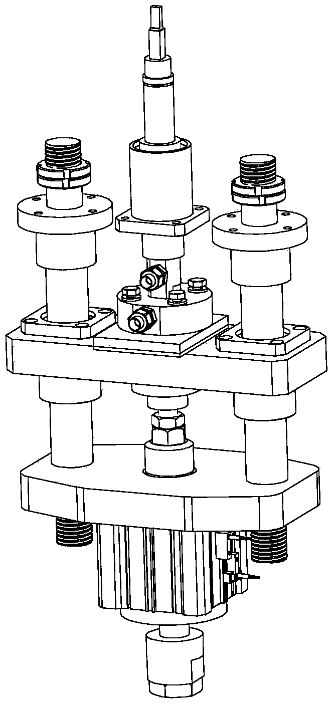
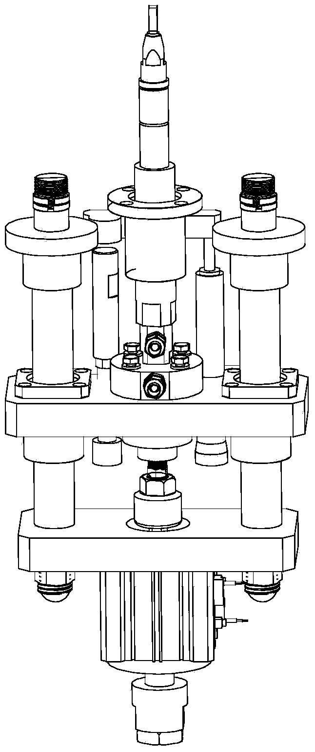
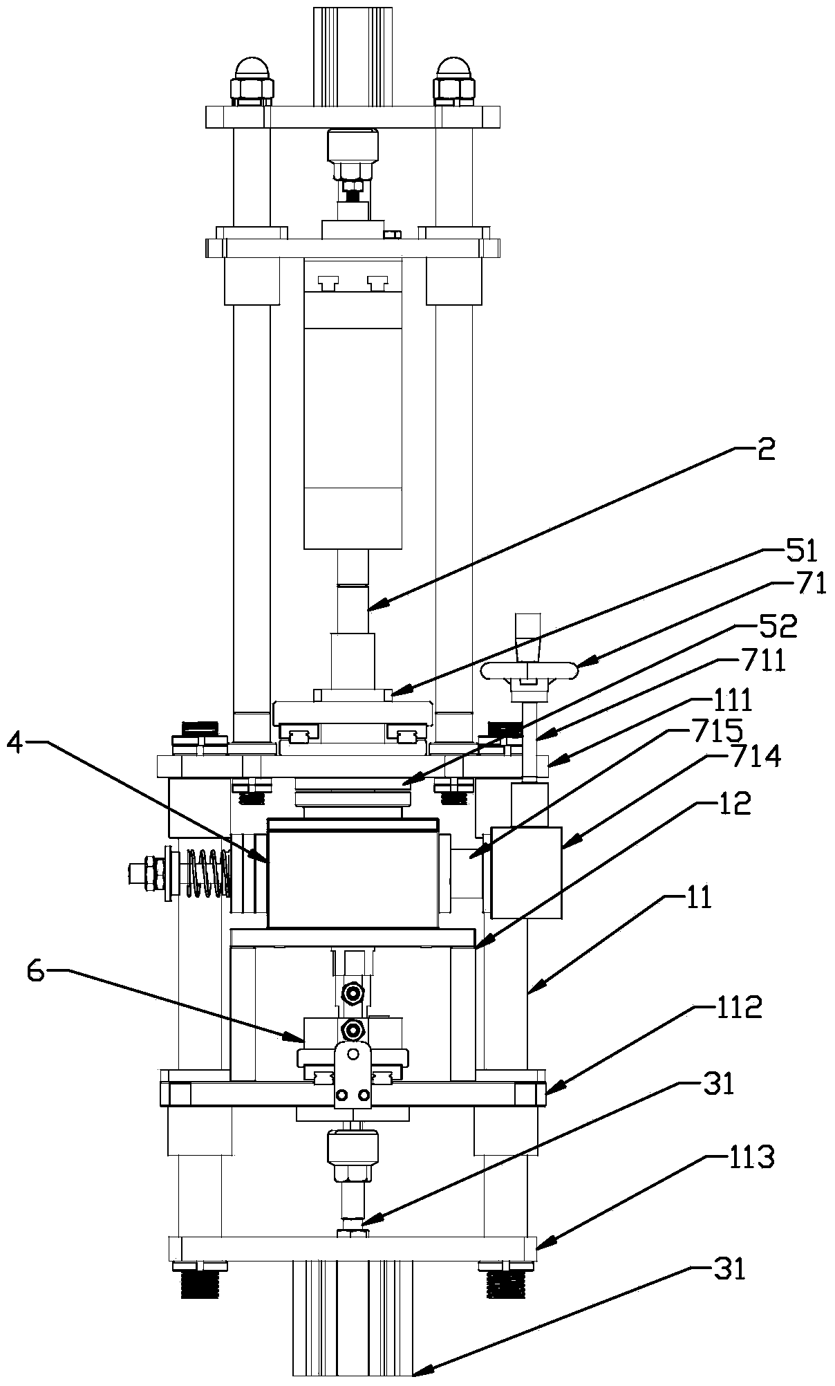
[0032] Specific embodiments of the present invention such as Figure 3-6 Shown is a welding mechanism with a lifting device, which includes a mounting frame, a welding head 2 and a lifting device. The lifting device includes a lifting cylinder 31 and a fine-tuning device 4. The mounting frame includes four columns 11, and the columns 11 are arranged sequentially from top to bottom. There are upper mounting plate 111, middle mounting plate 112 and lower mounting 113, upper mounting plate 111 is provided with positioning sleeve 51, fine-tuning device 4 is arranged on the middle mounting plate 112 by fine-tuning mounting bracket 12, fine-tuning mounting bracket 12 and middle mounting plate Also be provided with horizontal adjusting device 6 between 112, and lifting cylinder 31 is fixed on the lower mounting plate 113.

[0033] Above-mentioned fine-tuning device 4 comprises worm gear and worm transmission assembly, and worm gear 41 and worm screw 42 are mutually meshed and are pos...


PUM


Abstract

The invention discloses a welding mechanism with a lifting device. The welding mechanism comprises an installation frame, wherein a welding head and the lifting device for driving the welding head to move vertically are arranged on the installation frame, the lifting device comprises a lifting air cylinder and a vernier device, the lifting air cylinder is provided with a piston rod coaxial with the welding head, and the vernier device is arranged between the piston rod and the welding head. The welding mechanism with the lifting device has the advantages of being high in regulation accuracy, accurate in center positioning and convenient to operate.

Description

technical field [0001] The invention belongs to the technical field of spot welding machines, in particular to a welding mechanism with a lifting device in the spot welding machine. Background technique [0002] Spot welding machines usually use the principle of resistance heat to melt solid metal to form solder joints to weld low-voltage electrical appliances such as moving contacts, static contacts, wiring boards and guard plates in switch parts. The welding device in the spot welding machine includes an upper welding head and a lower welding head. In order to meet the welding needs of different accessories, the lower welding head is usually equipped with a lifting device that can adjust its height. Traditional lifting devices such as figure 1 As shown, the lifting cylinder is connected under the lower welding head. The lifting cylinder is fixed on the mounting plate of the welding device. There are mounting screws on the mounting plate. One end of the screw is fixedly co...

Claims


Application Information

Patent Timeline
Patent Type & Authority Applications(China)
IPC IPC(8): B23K11/11B23K11/36
CPCB23K11/115B23K11/31
Inventor 张根
Owner 浙江华亿电气有限公司
Why Eureka
Try Eureka