Vertically compensated stirring friction welding technique

A technology of vertical compensation and friction stirring, which is applied in the direction of welding equipment, manufacturing tools, non-electric welding equipment, etc., can solve the problems that the quality of weldments cannot be guaranteed, achieve good welding effect, good quality, and solve the effect of excessive weld gap

Active Publication Date: 2014-08-06
CRRC QINGDAO SIFANG CO LTD
View PDF6 Cites 15 Cited by
  • Summary
  • Abstract
  • Description
  • Claims
  • Application Information

AI Technical Summary

Problems solved by technology

For friction stir welding, the gap between the butt welds cannot exceed 1 / 10 of the plate thickness, otherwise the quality of the weldment cannot be guaranteed.

Method used


Image

  • Vertically compensated stirring friction welding technique
  • Vertically compensated stirring friction welding technique
  • Vertically compensated stirring friction welding technique

Examples


Embodiment 1

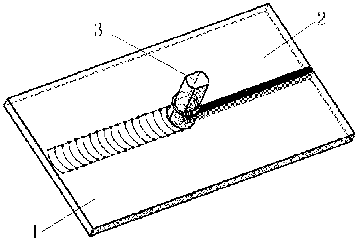
[0042] Such as figure 1 , figure 2 , image 3 As shown, a vertical compensation friction stir welding process method described in this embodiment is realized according to the following steps:

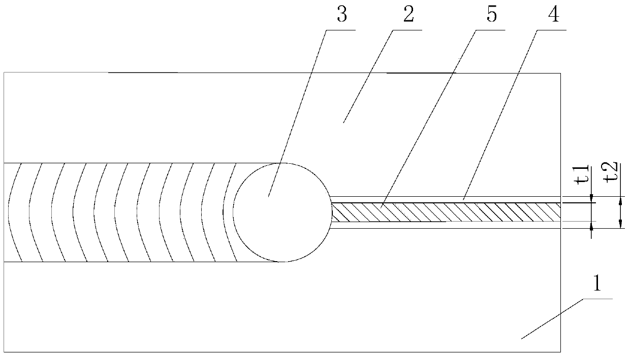
[0043] Step 1. Place the first weldment, the second weldment and the vertical compensation material 5 on the same horizontal plane (that is, combine the first weldment, the second weldment and the vertical compensation material 5), and clamp them with a fixture On the workbench; the first weldment and the second weldment are plates with the same thickness t; the absolute value of the difference between the height of the vertical compensation material 5 and the thickness t of the first weldment or the second weldment is less than 0.3mm , and the gap 4 width t between the first weldment and the second weldment 2 with compensating material 5 width t 1 The difference is less than 1 / 10 of the thickness of the first weldment.

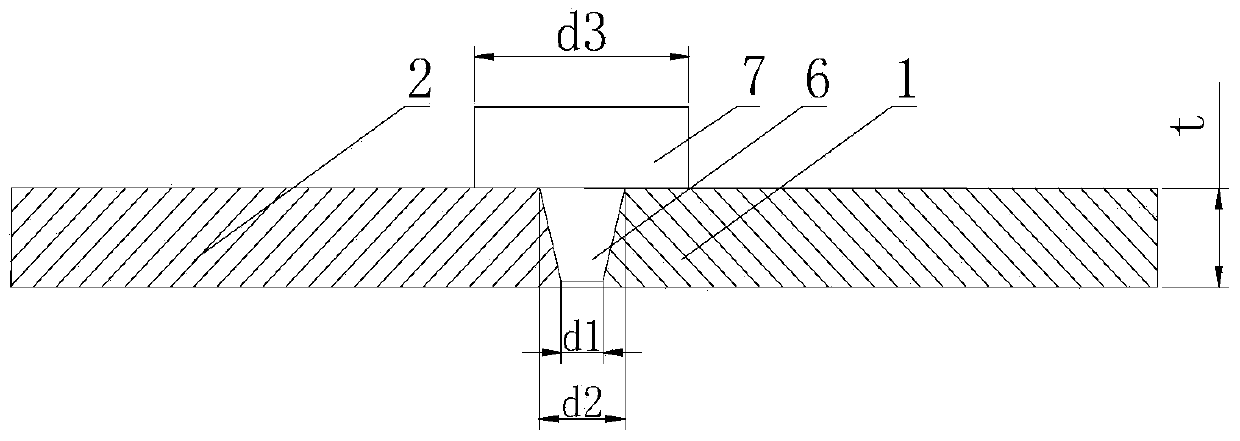
[0044] Step 2, the root diameter d of the stirring needle 6...

Embodiment 2

[0047] In step 2 of this embodiment, the rotation speed of the stirring head 3 is 1500 rpm. Other steps are the same as in Embodiment 1.

Embodiment 3

[0049] In step three of this embodiment, the stirring head 3 moves along the horizontal direction at a speed of 50 mm / min. Other steps are the same as in Embodiment 1.


PUM


Abstract

The invention relates to a vertically compensated stirring friction welding technique. Two welding pieces are placed on the same horizontal plane; a certain gap is formed between the two welding pieces; a vertically compensated material is placed in the gap; a stirring gap is controlled to rotate at a rotating speed of 500-5000 rpm; a stirring needle is stabbed into a to-be-welded portion of each welding piece; when reaching a set stabbing depth, the stirring needle stops stabbing and continues to rotate for 1-5 minutes; and the stirring head forwards moves along the horizontal direction of a connection surface of the welding pieces at a speed of 50-1500mm/min until welding is finished. The size of a shaft shoulder of the stirring head and the size of the stirring needle of the stirring head can be changed along with change of the size of the compensating material; the material has sufficient heat input and flows in a welding process, and a welding head with the excellent quality is obtained; and by using the stirring head, the compensating material and a to-be-welded material are sufficiently stirred and mixed, and welding, which is difficultly realized by using the conventional stirring friction method, on a large-gap butt joint can be realized.

Description

technical field [0001] The invention relates to the field of welding, in particular to a vertical compensation friction stir welding process method which can solve the problem of excessive weld seam gap. Background technique [0002] Friction stir welding is a new type of solid phase joining technology invented by TWI in the UK in 1991. Compared with conventional fusion welding methods, friction stir welding has the advantages of low stress, small deformation, low energy consumption, green and pollution-free. Of course, any welding method has its own advantages and disadvantages, while friction stir welding has disadvantages such as sufficient rigid support on the back and depressions with arc lines on the surface. In fact, the existence of these shortcomings has promoted the development of friction stir welding technology. At present, researchers at home and abroad have invented many new friction stir welding methods based on friction stir welding to meet different actual ...

Claims


Application Information

Patent Timeline
Patent Type & Authority Applications(China)
IPC IPC(8): B23K20/12B23K20/16
CPCB23K20/122B23K20/16
Inventor 路浩姬书得高双胜方喜风张铁浩汪认
Owner CRRC QINGDAO SIFANG CO LTD
Why Eureka
Try Eureka