Floating pressure head device

A floating indenter and indenter technology, applied in the field of press-fitting devices, can solve the problems of complex installation, long press-fitting time, and high cost, and achieve the effects of improving press-fitting accuracy, uniform press-fitting force, and convenient operation.

Inactive Publication Date: 2014-08-06
HEFEI UNIV OF TECH
View PDF6 Cites 6 Cited by
  • Summary
  • Abstract
  • Description
  • Claims
  • Application Information

AI Technical Summary

Problems solved by technology

[0002] In the mechanical press-fitting industry, when pressing multiple parts, the method often used is to vertically fix multiple indenters on a plate. When pressing parts, each indenter corresponds to multiple parts. , and then apply pressure to the entire plate, and transmit the pressure to the parts through the pressure head. In this method, the pressing force of multiple pressure heads is uneven, and the parts cannot be guaranteed to be in place at the same time, and the processing requirements are relatively high.
There is also a method of pressing multiple parts one by one. This method has many pressing steps, long pressing time and low efficiency.
Another method is to set up multiple driving sources, each corresponding to a part, but this method is costly and complicated to install

Method used


Image

  • Floating pressure head device
  • Floating pressure head device
  • Floating pressure head device

Examples


Embodiment Construction

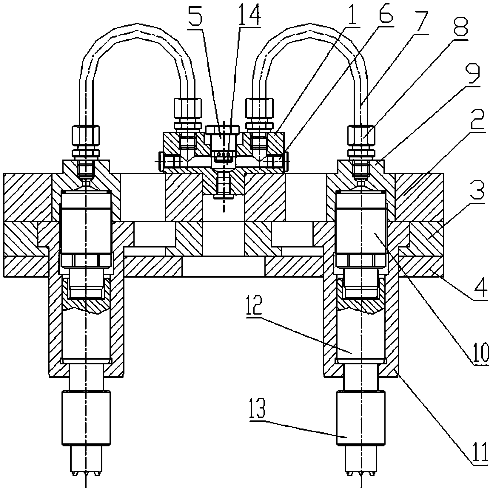
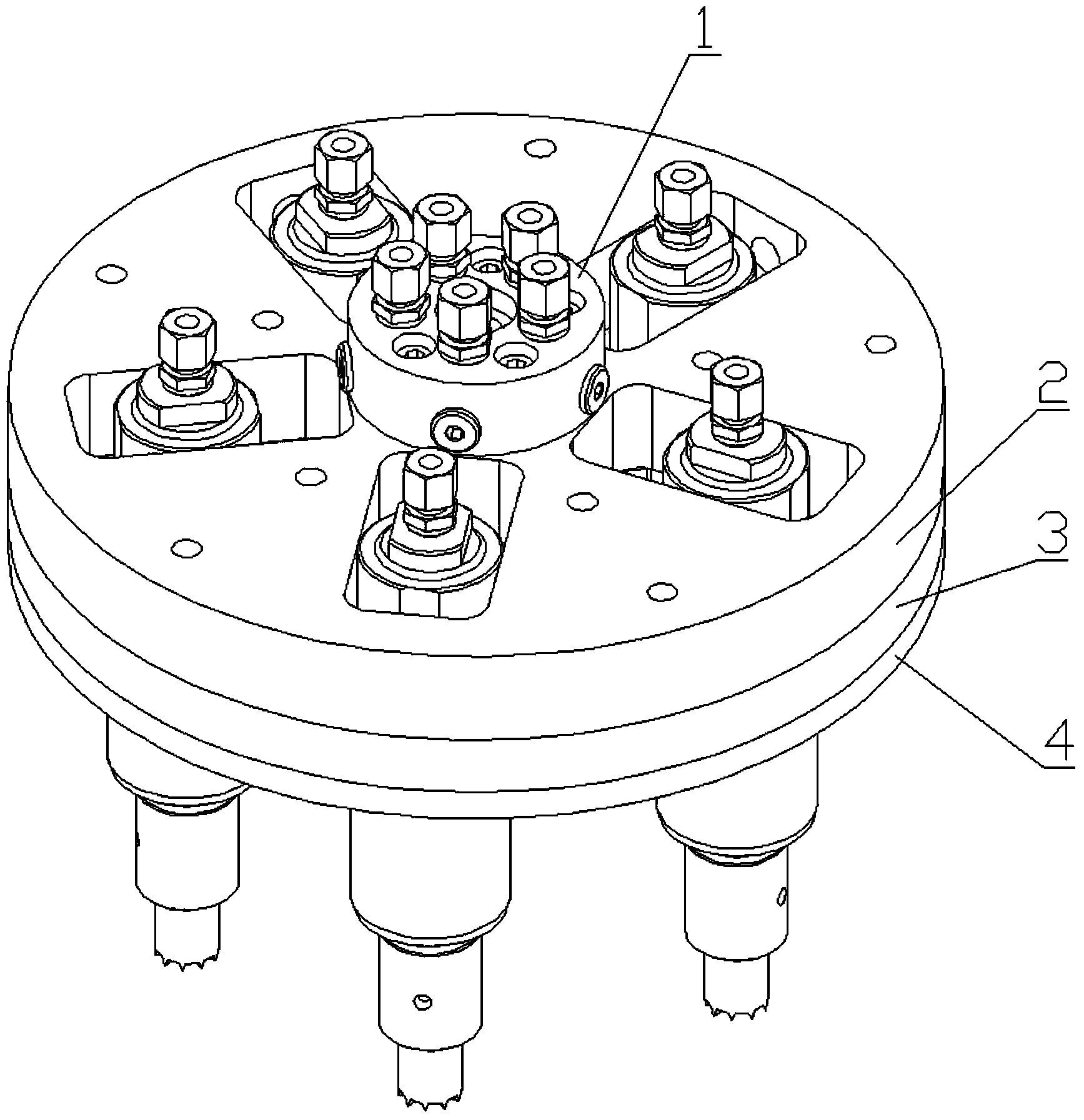
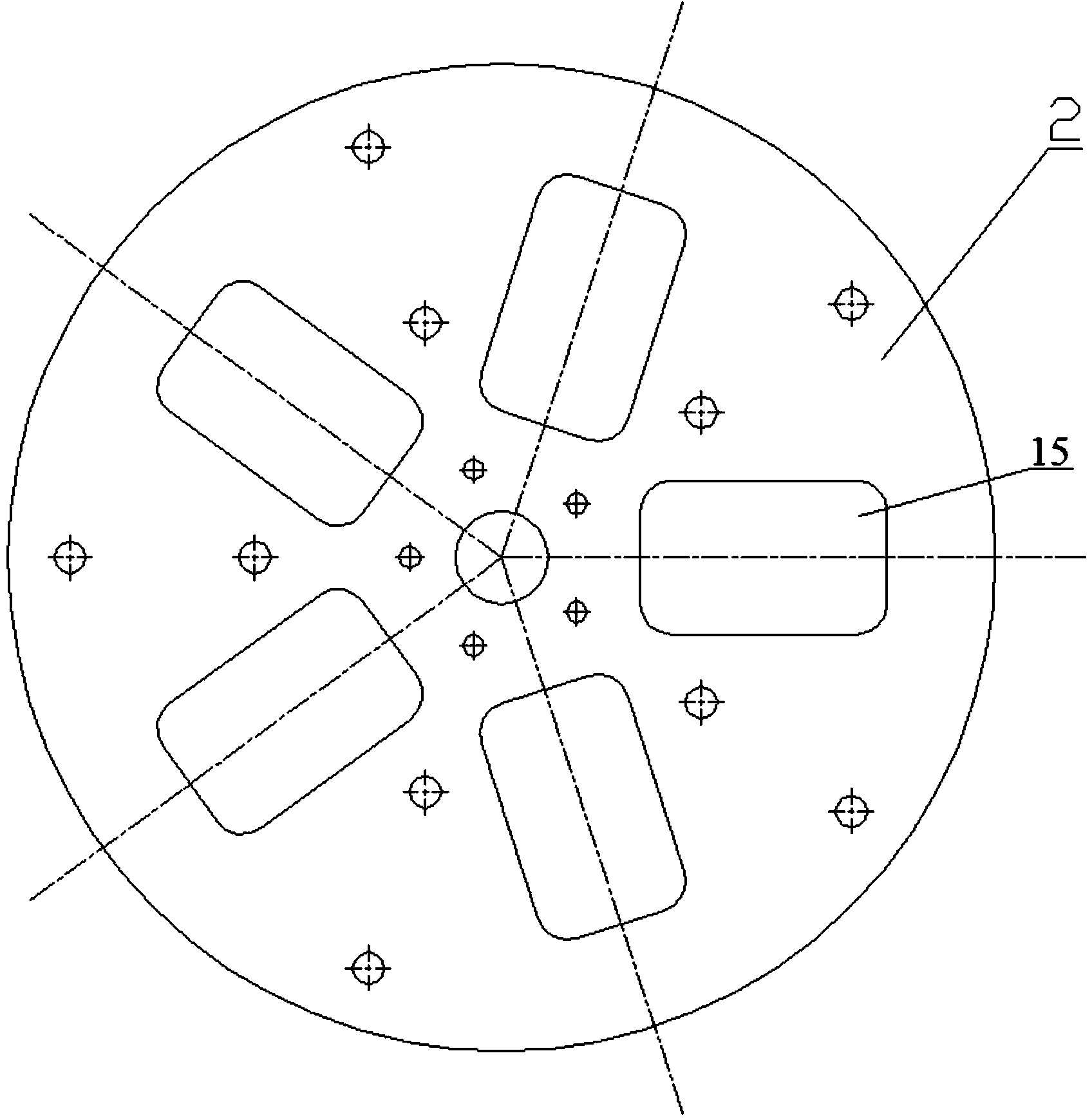
[0021] Referring to the accompanying drawings, a floating pressure head device includes sequentially stacked oil distribution seat 1, base 2, indexing plate 3 and positioning plate 4 and a plurality of pressure head assemblies, on the base 2 and indexing plate 3 A plurality of mounting grooves 15 are provided, and a plurality of pressure head assemblies are correspondingly arranged in a plurality of installation grooves 15, and each pressure head assembly can move horizontally in the mounting groove where it is located, and the oil distribution seat 1 is provided with There is a cavity 14, the oil distribution seat 1 is provided with an oil filling port leading to the cavity 14 and a check valve 5 is installed, and the oil distribution seat 1 is respectively provided with a plurality of oil outlets leading to the cavity 14, and a plurality of Hydraulic hoses 7 are correspondingly connected between the oil outlet and the plurality of pressure head assemblies.

[0022] In the pr...


PUM


Abstract

The invention discloses a floating pressure head device. The floating pressure head device comprises an oil distributing base, a base, an index plate, a positioning plate and multiple pressure head assemblies in a sequential overlaying mode. Multiple through installation grooves are formed in the base and the index plate. The pressure head assemblies are correspondingly arranged in the installation grooves. Each pressure head assembly can horizontally move in the corresponding installation groove. A cavity is formed in the oil distributing base, and the oil distributing base is provided with an oil filling port which leads to the cavity. A one-way valve is installed on the oil distributing base, and multiple oil outlets are respectively formed in the oil distributing base and lead to the cavity. Hydraulic hoses are correspondingly connected between the oil outlets and the pressure head assemblies. Hydraulic oil in all the pressure head assemblies is communicated, so that press fitting force of pressure heads of all the pressure head assemblies is even, press fitting is performed on each part in place, and press fitting precision is improved. Multiple parts can be pressed into the device in a one-off mode, so that time is saved, efficiency is improved, operation is convenient and cost is reduced, and the number of the pressure heads of all the pressure head assemblies can be designed according to workpieces.

Description

technical field [0001] The invention relates to the field of press-fitting devices, in particular to a high-precision floating press head device for simultaneously press-fitting multiple parts. Background technique [0002] In the mechanical press-fitting industry, when pressing multiple parts, the method often used is to vertically fix multiple indenters on a plate. When pressing parts, each indenter corresponds to multiple parts. , and then apply pressure to the entire plate, and transmit the pressure to the parts through the pressure head. In this method, the pressing force of multiple pressure heads is uneven, and the parts cannot be guaranteed to be in place at the same time, and the processing requirements are relatively high. There is also a method of press-fitting multiple parts one by one. This method has many press-fit steps, long press-fit time and low efficiency. Another method is to set multiple driving sources, each corresponding to a part, but this method is ...

Claims


Application Information

Patent Timeline
Patent Type & Authority Applications(China)
IPC IPC(8): B23P19/027
CPCB23P19/027
Inventor 任永强石大勇汪超
Owner HEFEI UNIV OF TECH
Why Eureka
Try Eureka