Supercharge Your Innovation With Domain-Expert AI Agents!

Scanning head of a laser marking machine

A technology of laser marking machine and scanning head, which is applied in the field of scanning head to achieve the effect of easy maintenance and handling, preventing water leakage and overcoming the deviation of swing angle

Active Publication Date: 2016-01-20
GUANGZHOU NEW CKLASER CO LTD
View PDF5 Cites 0 Cited by
  • Summary
  • Abstract
  • Description
  • Claims
  • Application Information

AI Technical Summary

Problems solved by technology

[0004] In order to solve the above shortcomings, the present invention designs a scanning head of a laser marking machine, which overcomes the phenomenon of temperature drift caused by excessive temperature during the marking process, and greatly improves the marking accuracy and safety

Method used


Image

  • Scanning head of a laser marking machine
  • Scanning head of a laser marking machine
  • Scanning head of a laser marking machine

Examples


Embodiment Construction

[0034] The specific embodiment of the present invention will be further described below in conjunction with accompanying drawing:

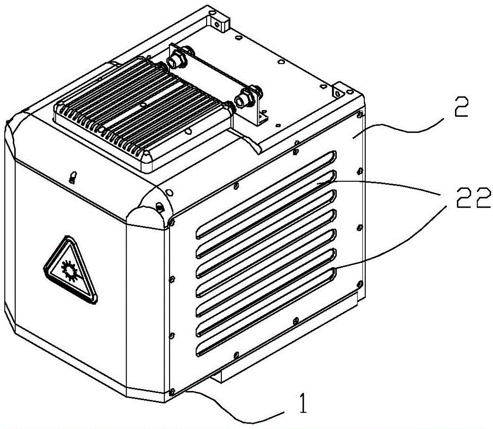
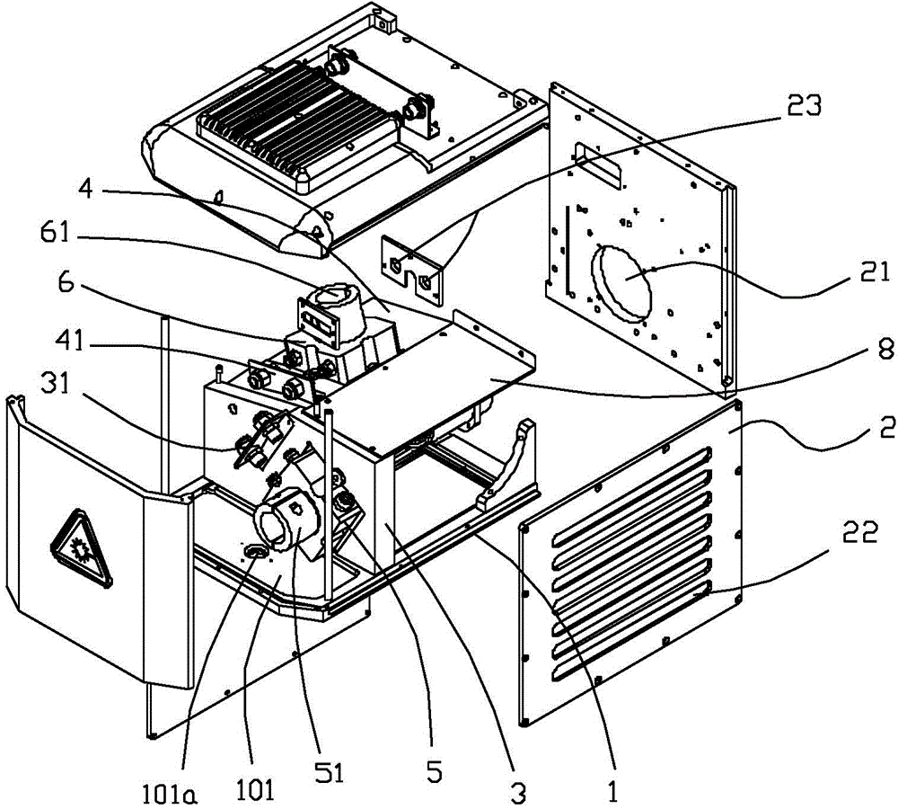
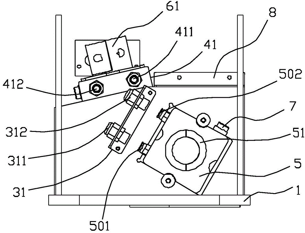
[0035] Refer to attached figure 1 to attach Figure 4 As shown, a scanning head of a laser marking machine includes a base plate 1, a housing 2 and a scanning system arranged on the base plate 1, the housing 2 is covered on the base plate 1, and the housing 2 is provided with The laser entrance 21 is corresponding to the laser exit on the bottom plate 1 . The scanning system includes a first support plate 3 and a second support plate 4, the first support plate 3 is vertically arranged on the bottom plate 1; One side of a support plate 3 is vertically connected, and the vertical connection means that the horizontal plane where the connection line between the second support plate 4 and the first support plate 3 is located is perpendicular to the first support plate 3 . The upper end of the first support plate 3 is provided with an oblique angle c...


PUM


Abstract

The invention discloses a scanning head of a laser marking machine. The scanning head comprises a first water cooling base, a second water cooling base, a first fixing part and a second fixing part, wherein the first water cooling base and the second water cooling base are installed on a first supporting plate and a second supporting plate respectively. A water duct in the first water cooling base is communicated with a water duct in the second water cooling base through a water pipeline, the water pipeline penetrates through the fixing parts to be perpendicularly connected into connectors on water inlets of the water cooling bases and connectors on water outlets of the water cooling bases to form a water cooling circulating channel. It is avoided that due to too high temperature, the swing angle of a lens deviates, water leakage at the joints of the water pipeline is effectively avoided, and marking quality and equipment stability are improved. Meanwhile, if accidental water leakage occurs and water drops to marked objects through a ponding tank, operators can find the situation in time and shut down for maintenance, and safety is greatly improved. The water cooling bases, the fixing parts, the first supporting plate and the second supporting plate are matched with one another, so that the size of the scanning head is greatly reduced.

Description

technical field [0001] The invention relates to the field of laser marking equipment, in particular to a scanning head of a laser marking machine. Background technique [0002] At present, some laser marking machines on the market use a servo motor to drive the laser scanning lens to swing to adjust the angle of the laser beam. However, due to the high-speed operation of the scanning lens during the marking process, the temperature rises rapidly, and the accumulation of heat It is easy to cause changes in the properties of the laser working medium and affect the quality of the output laser beam. If the heat cannot be discharged in time, the temperature in the cavity will continue to rise, which will affect the normal operation of the laser marking machine, and there will be certain safety hazards, so the temperature control of the scanning head of the laser marking machine is the key to the long-term operation of the laser. Guarantee of efficient work on time. [0003] In ...

Claims


Application Information

Patent Timeline
Patent Type & Authority Patents(China)
IPC IPC(8): B41J2/435B41J29/377
Inventor 徐强
Owner GUANGZHOU NEW CKLASER CO LTD
Features
  • R&D
  • Intellectual Property
  • Life Sciences
  • Materials
  • Tech Scout
  • Unparalleled Data Quality
  • Higher Quality Content
  • 60% Fewer Hallucinations
Learn More