
Anti-collision self-resetting boundary frame for overspan highway railway bridge

A road and railway bridge, self-resetting technology, applied to roads, roads, restricted traffic and other directions, can solve problems such as potential safety hazards, and achieve the effects of strong applicability, stable protection, and prolonged action time

Inactive Publication Date: 2016-08-03
中国铁路济南局集团有限公司青岛工务段
View PDF5 Cites 0 Cited by
  • Summary
  • Abstract
  • Description
  • Claims
  • Application Information

AI Technical Summary

Problems solved by technology

However, the current structure of the existing bounded frame cannot meet the above technical requirements, and there are potential safety hazards in use

Method used


Image

  • Anti-collision self-resetting boundary frame for overspan highway railway bridge
  • Anti-collision self-resetting boundary frame for overspan highway railway bridge
  • Anti-collision self-resetting boundary frame for overspan highway railway bridge

Examples


Embodiment 1

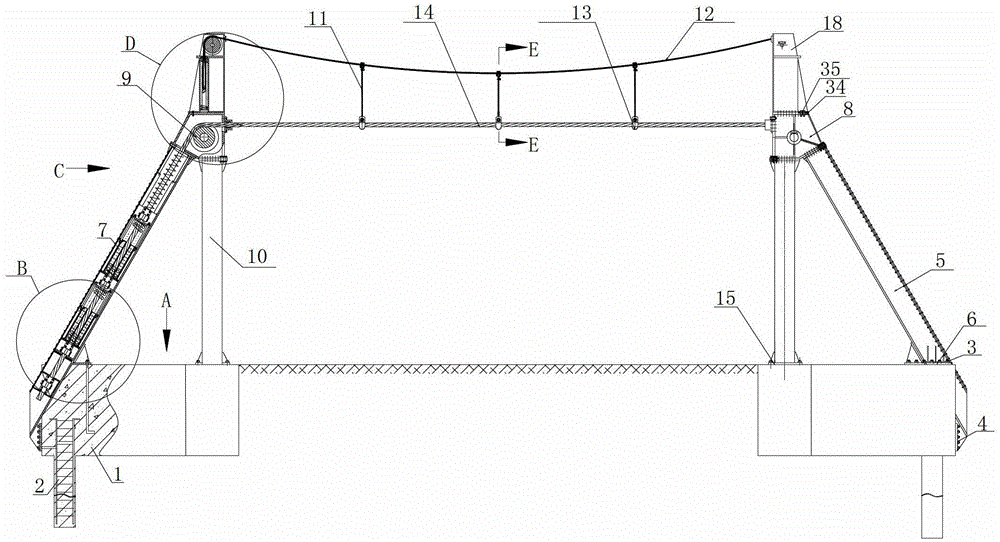
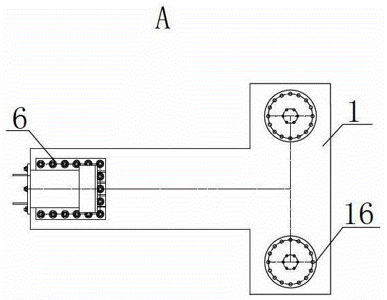
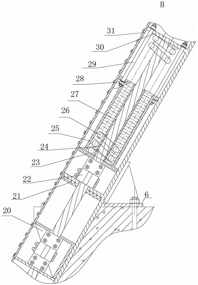
[0031] Such as figure 1 As shown, the anti-collision self-resetting limit frame of the over-span highway railway bridge includes a U-shaped beam 5, an A-shaped mast 10, a support 18, an adjustment seat 8, an intercepting steel cable 14 and a cable-stayed positioning cable 12, and the U-shaped beam 5 and the bottom end of the A-shaped mast frame 10 are fixed on the concrete foundation 1. The A-shaped masts 10 are respectively located on both sides of the lower part of the upper-span highway railway bridge, and are parallel to the road. The outer sides of the A-shaped masts 10 are respectively provided with U-shaped beams 5, and the U-shaped beams 5 on both sides of the road are arranged symmetrically. The mast 10 is vertically arranged, the U-shaped beam 5 is arranged obliquely, and the included angle between the U-shaped beam 5 and the vertical direction can be any angle of 30°-90°. The top of the A-shaped mast 10 is provided with a support 18 , and the U-shaped beam 5 , the ...

Embodiment 2

[0041] In this embodiment, the angle between the U-shaped beam and the vertical direction is 0°, that is, the U-shaped beam is in the vertical direction. Now the U-shaped beam is positioned in the pipe of one of the lower brackets 19, and the top of the bracket 18 is provided with a horizontal jack 41, by which the horizontal jack 41 can balance and intercept the power in the steel cable on the one hand, and also can be used to fix the whole Boundary frame.

[0042] When the angle between the U-shaped beam and the vertical direction is small, a horizontal jack bar can also be fixedly arranged on the top of the support.

[0043] Others are the same as embodiment 1.


PUM


Abstract

The invention relates to a height limit frame on a road, in particular to an anti-collision self-resetting clearance limit frame on an overpass highway / railway. The clearance limit frame comprises an interception steel cable, U-shaped beams, A-shaped mast frames, brackets, fixing and adjusting seats and a positioning stay cable, wherein the bottom ends of both the U-shaped beams and the A-shaped mast frames are fixed on concrete foundations; the A-shaped mast frames are positioned on two sides of a highway respectively and are parallel to the highway; the U-shaped beams are arranged on the outer sides of the A-shaped mast frames respectively; the A-shaped mast frames are arranged vertically; the included angle between the U-shaped beams and the vertical direction is 0-90 degrees; the brackets are arranged above the A-shaped mast frames; the U-shaped beams, the A-shaped mast frames and the brackets are connected through the fixing and adjusting seats; dampers are arranged in the U-shaped beams; the interception steel cable is arranged over the highway; the two ends of the interception steel cable are arranged in the U-shaped beams on two sides of the highway respectively and fixedly connected the dampers; the positioning stay cable is arranged at the top ends of the brackets and positioned above the interception steel cable. The clearance limit frame is simple in structure, plays a role in forcing super-elevation cars to stop, and better guarantees the driving safety of a railway.

Description

technical field [0001] The invention relates to a limit elevated frame for roads, in particular to an anti-collision self-resetting limit frame for an upper-span highway and railway bridge. Background technique [0002] The boundary frame is a structure that is set above the road to limit the height of passing vehicles in order to protect structures such as bridges and culverts in front. If the vehicle exceeds the allowable height of the bridge and culvert, all passing is prohibited. Most of the bridge protective frames currently in use are rigid structures, welded with section steel or steel pipes, and the boundary frame structure is very rigid. When a large vehicle exceeds the height of the boundary frame and collides with the boundary protection frame, effective deformation cannot occur. The huge impact force generated in an instant destroys the protective frame. If the limit frame structure is knocked down, it will cause a safety accident and threaten the safety of pede...

Claims


Application Information

Patent Timeline
Patent Type & Authority Patents(China)
IPC IPC(8): E01F13/12
Inventor 岳言贵王友群刘继泉丁军高祀鹤赵文波盖筱青王群冷代森刘化忠
Owner 中国铁路济南局集团有限公司青岛工务段
Learn More