Automatic brake control system

A technology of automatic braking and control system, which is applied in the fields of production fluids, wellbore/well components, earth-moving drilling and mining, etc., and can solve problems such as potential safety hazards, top-rushing, and ground-impacting

Inactive Publication Date: 2014-08-06
HENAN XINYU PETROLEUM MACHINERY MFG
View PDF14 Cites 2 Cited by
  • Summary
  • Abstract
  • Description
  • Claims
  • Application Information

AI Technical Summary

Problems solved by technology

[0002] At present, the known brake system is a manual braking device. If no one is on duty at the scene when the pumping unit is powered off due to the power grid, due to the inertia of the pumping unit, the counterweight of the pumping unit will continue to run according to the original direction of motion, which will Accidents of rushing to the top and hitting the ground occurred, posing safety hazards

Method used


Image

  • Automatic brake control system
  • Automatic brake control system
  • Automatic brake control system

Examples


Embodiment Construction

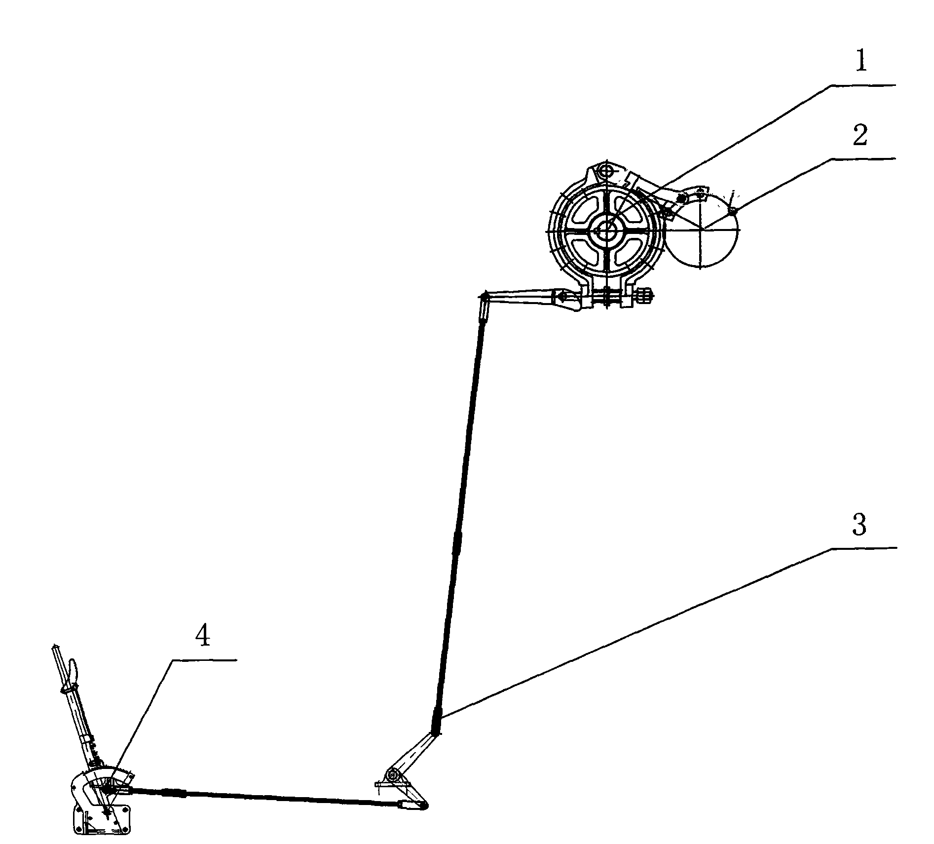
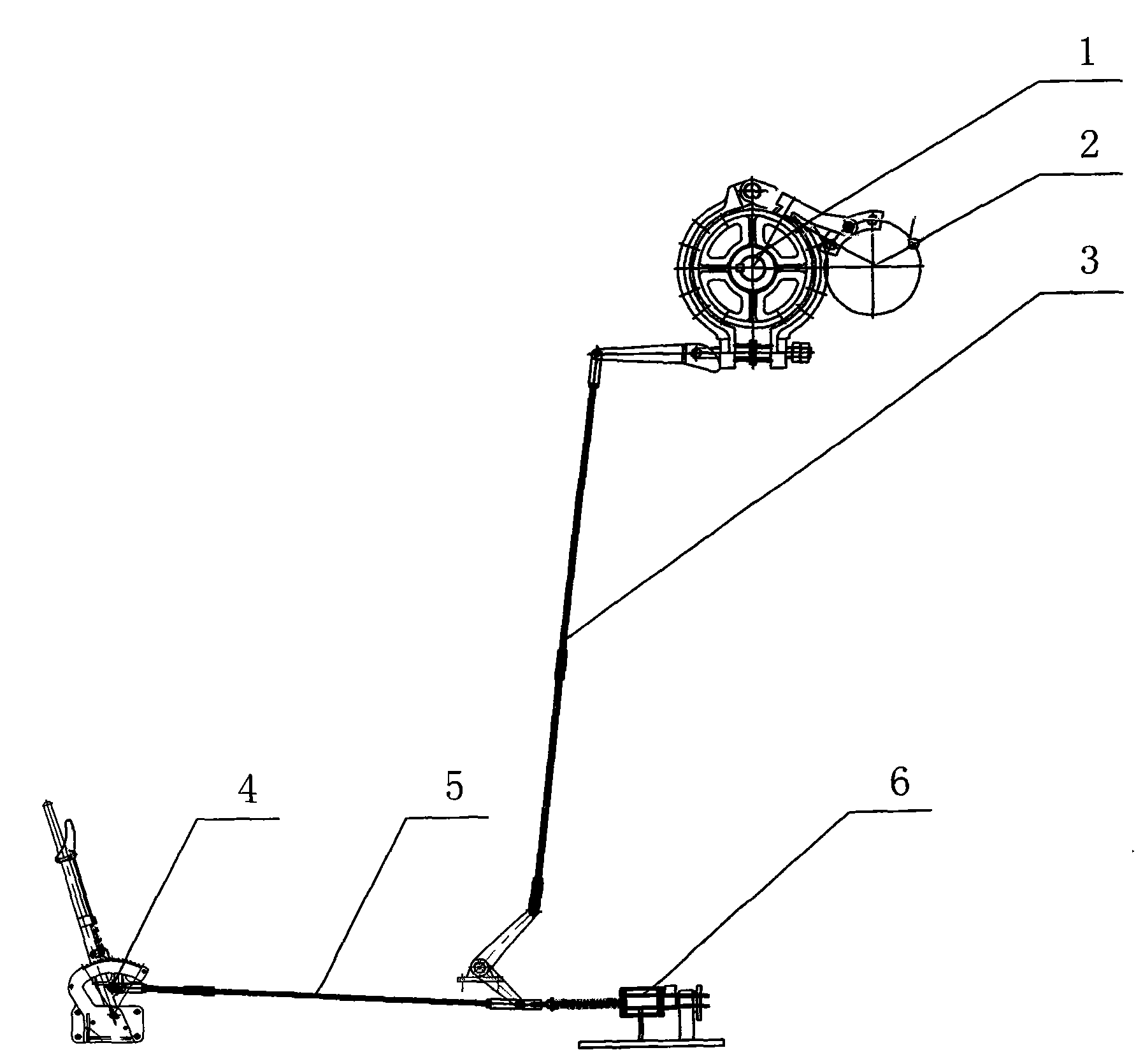
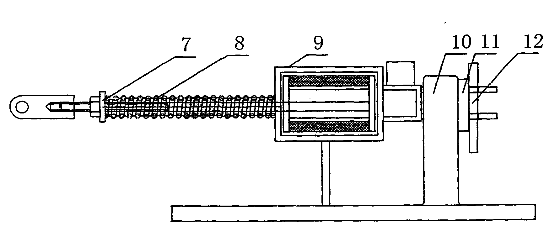
[0010] exist figure 2 In the embodiment, by improving the braking system of the original pumping unit, an automatic braking device is added on the basis of the original pumping unit. The device consists of a pressure spring 8, an electromagnetic coil 9, a base 10, an adjusting gasket 11, Cylindrical pin 12 etc. are formed. When the pumping unit stops: the electromagnetic coil 9 is powered off, and the suction disappears, and the push rod 7 is promoted under the action of the spring 8, so that the connecting rod device 3 moves downward, the brake is applied, and the pumping unit stops working. When the pumping unit starts: first release the handbrake device, the electromagnetic coil 9 is energized, generates magnetic force, pulls the push rod 7, makes the connecting rod device 3 move upwards, releases the brake device 1, and the pumping unit operates normally. If the machine is maintained and needs to stop working for a long time, pull on the manual brake device 4, stop the p...


PUM


Abstract

An automatic brake control system comprises a brake device, a parking insurance device, a connection rod device, an automatic control device, a connection steel wire rope, a hand brake device and the like. The automatic control device is composed of a push rod, a compression spring, an electromagnetic coil, a machine base, an adjusting gasket and a cylinder pin. The base is a carrier and is arranged on a pumping unit machine base, one end of the push rod is connected with a steel wire rope connector, the other end of the push rod is arranged on the compression spring in a sleeved mode and inserted into a center hole of the electromagnetic coil, and the cylinder pin is inserted into the right side of the machine base after a gasket gap is adjusted properly. The hand brake device is connected with the automatic control device through the flexible steel wire rope. According to the system, a motor can be braked in time during artificial parking, and a brake function can be achieved during a power grid failure without human intervention. Safety accidents caused by brake do not exist, the safety hidden hazard caused due to the fact that people forget to pull a hand brake is not caused, and the automatic brake control system is safe and reliable.

Description

technical field [0001] The invention relates to an oil field petroleum machinery, in particular to a brake control system of a tower pumping unit. Background technique [0002] At present, the known brake system is a manual braking device. If no one is on duty at the scene when the pumping unit is powered off due to the power grid, due to the inertia of the pumping unit, the counterweight of the pumping unit will continue to run according to the original direction of motion, which will Accidents of rushing to the top and hitting the ground occurred, posing potential safety hazards. Contents of the invention [0003] In order to overcome the above-mentioned defects of the existing braking system, the present invention provides an automatic braking control system, which not only can brake the pumping unit in time when artificially stopped, but also can automatically Play a timely braking effect. It will not be unable to brake due to braking, causing safety accidents on sit...

Claims


Application Information

Patent Timeline
Patent Type & Authority Applications(China)
IPC IPC(8): E21B43/00
Inventor 高利兵廖大林李要民董丽丽王会萍张明忠
Owner HENAN XINYU PETROLEUM MACHINERY MFG
Why Eureka
Try Eureka