Stop valve

A globe valve and valve core technology, which is applied in the field of air conditioner globe valves, can solve the problems that the collar and the valve core cannot be effectively fitted, the globe valve fails, and the deviation of the coaxiality of the collar 3 is too large, so as to reduce the thermal deformation. Influence, stable sealing effect, effect of expanding heat dissipation area

Active Publication Date: 2014-08-06
ZHEJIANG DUNAN MASCH CO LTD
View PDF7 Cites 0 Cited by
  • Summary
  • Abstract
  • Description
  • Claims
  • Application Information

AI Technical Summary

Problems solved by technology

Otherwise, the deviation of the coaxiality of the collar 3 is too large, or the large deformation caused by heat during welding may cause the collar and the valve core to not fit effectively, and the sealing effect cannot be achieved well, resulting in the failure of the stop valve
Of course, it is also possible to increase the closing torque of the spool to achieve closing and sealing. At this time, the risk of efficiency and life is inevitable.

Method used


Image

  • Stop valve
  • Stop valve
  • Stop valve

Examples


Embodiment Construction

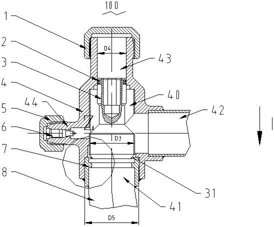
[0021] see Figure 2 to Figure 4 , the structure and assembly method of the shut-off valve 100 of the present invention will be described below with reference to the accompanying drawings.

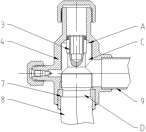
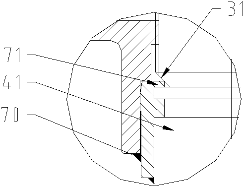
[0022] The shut-off valve 100 of the present invention includes a cavity 40 formed by assembling a valve seat 4 and a valve core 3 and a collar 7 installed on the valve seat 4. The valve seat 4 has a medium inlet 41 and a medium outlet 42. The collar 7 is provided with a first sealing ring part 71 located between the medium inlet 41 and the medium outlet 42, the valve core is located between the medium inlet 41 and the medium outlet 42 and can cooperate with the first sealing ring part 71 To realize the on-off of the medium inlet 41 and the medium outlet 42, the valve core 3 is also provided with a tapered surface 31 that cooperates with the first sealing ring part 71, and the collar 7 has a normal hole diameter D1, a normal inner wall thickness S1 and a formed The second aperture D2 of t...


PUM


Abstract

The invention discloses a stop valve. The stop valve comprises a cavity and a lantern ring, wherein the cavity is defined by assembled a valve seat and a valve element; the lantern ring is mounted on the valve seat; the valve seat comprises a medium inlet and a medium outlet; a first sealing ring part located between the medium inlet and the medium outlet is arranged on the lantern ring; the valve core is located between the medium inlet and the medium outlet, and can coordinate with the first sealing ring part to switch on / off the medium inlet and the medium outlet; the stop valve is characterized in that a conical surface matched with the first sealing ring part is arranged on the valve element; the lantern ring is of normal pore diameter, normal inner wall thickness and a second pore diameter forming the first sealing ring part; the second pore diameter is smaller than the normal pore diameter; a radiating ring part which is in interval with the first sealing ring part is further arranged on the lantern ring. The two ring parts are arranged on the lantern ring of the stop valve, so that the radiating area can be effectively increased, the influence scope of thermal distortion can be reduced, and the stable sealing effect can be achieved.

Description

technical field [0001] The invention relates to the refrigeration field, and more specifically relates to an air conditioner cut-off valve. Background technique [0002] see figure 1 An existing cut-off valve structure is disclosed, which includes a cavity formed by assembling the valve seat 4 and the valve core 3 and a collar 7 installed on the valve seat. The valve seat 4 is provided with an upper Sealing surface A, the two ends of the valve seat 4 are respectively connected to the medium inlet connecting pipe 8 and the medium outlet connecting pipe 9, and the collar 7 in the cavity is provided with a lower sealing surface between the medium inlet and the outlet, Between the upper sealing surface A and the lower sealing surface, a valve core 3 that can generate displacement is arranged to divide the cavity into an upper chamber C and a lower chamber D, and the valve core 3 is respectively provided with the upper sealing surface A. Fitting taper and lower sealing face fit...

Claims


Application Information

Patent Timeline
Patent Type & Authority Applications(China)
IPC IPC(8): F16K1/00F16K1/38F16K1/42F16K49/00
CPCF16K1/00F16K1/38F16K1/42
Inventor 李维槽宣永斌葛存奇
Owner ZHEJIANG DUNAN MASCH CO LTD
Why Eureka
Try Eureka