Vertical-installation multifunctional air valve device

A vertically installed, multi-functional technology, applied in the direction of airflow control components, etc., can solve the problem of entering the station, sometimes entering the tunnel from the station, and achieve the effect of reducing energy consumption and saving energy

Active Publication Date: 2014-08-06
CHINA RAILWAY DESIGN GRP CO LTD
6 Cites 9 Cited by

AI-Extracted Technical Summary

Problems solved by technology

However, due to the two-way direction of the piston wind, sometimes it enters the station from the tunnel, and sometimes enters the tunnel from the station. At ...

Method used

[0030] One end of each self-suspended movable blade 7 is provided with a small shaft 8, and the self-suspended movable blade 7 takes the small shaft 8 as a fulcrum for rotation. The self-suspended movable blade 7 is provided with a plurality of ribs 11, and the ribs 11 can enhance the strength of the blade, and can also increase the sealing performance of the self-suspended movable blade 7 and the small shaft 8. A fixed baffle 12 is provided on the lower frame ...

Abstract

The invention provides a vertical-installation multifunctional air valve device. The vertical-installation multifunctional air valve device comprises a valve body framework, a division board and self-drooping movable blades. The valve body framework is divided into a left channel and a right channel by the division board in the center of the valve body framework, a group of self-drooping movable blades which can be opened only in one direction are arranged inside each channel, and the opening direction of the self-drooping movable blades in one channel is opposite to the opening direction of the self-drooping movable blades in the other channel. The upper end and the lower end of the valve body framework are provided with two slideways respectively, a sliding valve plate is arranged in each slideway, the size of each sliding valve plate is the same as that of each channel opening, and through movement of the two sliding valve plates and opening of the self-drooping movable blades, the direction of airflow inside an air valve is controlled and changed or the airflow is stopped from flowing. According to the vertical-installation multifunctional air valve device, the problem that an electric air valve can not control the direction of piston wind in a subway station is solved, a shielded gate and an open/closed environmental control system of the subway station are organically combined, energy consumption of the environmental control system of the subway station in the operation process is effectively reduced, and energy is saved.

Application Domain

Air-flow control members

Technology Topic

PistonAirflow +6

Image

  • Vertical-installation multifunctional air valve device
  • Vertical-installation multifunctional air valve device
  • Vertical-installation multifunctional air valve device

Examples

  • Experimental program(1)

Example Embodiment

[0025] The technical solution of the present invention will be further described below in conjunction with the accompanying drawings.
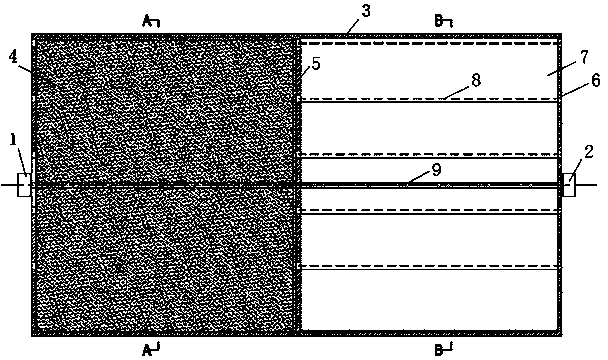
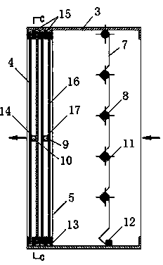
[0026] figure 1 It is a structural diagram of the vertically installed multifunctional air valve device of the present invention; figure 2 with image 3 The internal structure diagram of the air valve device; Figure 4 It is the internal structure diagram of the slide structure. Such as Figure 1 to Figure 4 As shown, the vertically installed multifunctional air valve device of the present invention includes a valve body frame 3, a partition plate 5, a self-verting movable blade 7, a sliding valve plate and a transmission mechanism. The valve body frame 3 is divided into two left and right channels by a central partition plate 5. Each channel is provided with a set of self-suspending movable blades 7 that can only be opened in one direction, and the opening directions of the self-suspending movable blades in the two channels in contrast. The upper end and the lower end of the valve body frame 3 are respectively provided with two slideways, each slideway is provided with a sliding valve plate, and the size of the sliding valve plate is the same as the size of each channel port. The sliding valve plate can move left and right in the slideway to close the left channel or the right channel, thereby changing the flow direction of the air flow in the air valve or blocking the flow of the air flow.
[0027] The first sliding valve plate 4 is arranged in the outer slideway. The upper and lower ends of the sliding valve plate are provided with three rollers 15 that can roll in the outer slideway and restrict the first sliding valve plate 4 in the outer slideway. A first sliding block 14 and a first screw 10 are arranged inside the first sliding valve plate 4. An internal thread is formed in the center of the first slider 14 to be sleeved on the first screw 10, and the outside is fixedly connected to the first sliding valve plate 4, and the first screw 10 is connected to the first motor 1. The first motor 1 drives the first screw 10 to rotate, and drives the first sliding block 14 to move radially, so that the first sliding valve plate 4 moves in the outer slideway.
[0028] The second sliding valve plate 16 is arranged in the inner slideway, and the upper and lower ends of the sliding valve plate are provided with three rollers 15 which can roll in the inner slideway and restrict the second sliding valve plate 16 in the outer slideway. A second sliding block 17 and a second screw 9 are provided inside the second sliding valve plate 16. The second sliding block 17 is formed with an internal thread in the center and sleeved on the second screw 9, and externally fixedly connected to the second sliding valve plate 16, and the second screw 9 is connected to the second motor 2. The second motor 2 drives the second screw 9 to rotate, and drives the second slider 17 to move radially, so that the second sliding valve plate 16 moves in the inner slideway.
[0029] The above-mentioned first sliding valve plate 4 and second sliding valve plate 16 are both composed of two layers of plates, and an internal threaded sliding block arranged in the middle is welded and fixed to the valve plate.
[0030] A small shaft 8 is provided at one end of each self-suspending movable blade 7, and the small shaft 8 is used as a rotation fulcrum of the self-suspending movable blade 7. The self-hanging movable blade 7 is provided with a plurality of ribs 11, which can increase the strength of the blade, and can also increase the sealing performance of the self-hanging movable blade 7 and the small shaft 8. A fixed baffle plate 12 is provided on the lower frame of the valve body frame 3 corresponding to the position of the self-suspending movable blade 7 to restrict the return of the self-suspending movable blade 7. Therefore, the self-hanging movable blade can only be opened in one direction. Such as figure 2 with image 3 As shown, the setting directions of the self-suspending movable blades in the two channels are opposite, and therefore, the opening directions of the self-suspending movable blades in the two channels are also opposite.
[0031] The working principle of the vertically installed multifunctional air valve device of the present invention is as follows:
[0032] The left channel is provided with a self-hanging movable blade that can only be opened outward, and the right channel is provided with a self-hanging movable blade that can only be opened inward, and the self-hanging sliding blade uses a small shaft as a rotation fulcrum. When the two sliding valve plates are moved to the left channel of the damper and the pressure on the outside of the damper is higher than the pressure on the inside, the self-hanging movable blade in the right channel of the damper is automatically opened inward. When the pressure is opposite, the self-hanging movable vane automatically closes, thereby realizing the air flow from the outside to the inside. When the two sliding valve plates are moved to the right side of the damper and the pressure on the outside of the damper is lower than the pressure inside, the self-sagging movable vane in the left channel of the damper automatically opens outwards, and the self-sagging movable vane automatically closes when the pressure is opposite , So as to achieve air flow from the inside to the outside. When the two valve plates are moved to the two channels respectively, the air valve is closed.
[0033] The description in the above specification is only the specific implementation of the present invention, and the illustration does not limit the essential content of the present invention. Therefore, all corresponding modifications and equivalents that may be utilized belong to the scope of the patent application of the present invention.

PUM

no PUM

Description & Claims & Application Information

We can also present the details of the Description, Claims and Application information to help users get a comprehensive understanding of the technical details of the patent, such as background art, summary of invention, brief description of drawings, description of embodiments, and other original content. On the other hand, users can also determine the specific scope of protection of the technology through the list of claims; as well as understand the changes in the life cycle of the technology with the presentation of the patent timeline. Login to view more.

Similar technology patents

Closed thermal cycle water tank central air conditioning system

InactiveCN109268979AReduce operating energy consumptionlow running cost
Owner:王俊杰

Multi-working-condition air heat and humidity coupling treatment equipment

PendingCN113251514AReduce operating energy consumptionReduce energy consumption
Owner:GUIZHOU CONSTR SCI RES & DESIGN INST OF CSCEC

Elevation-type micro-power MBR apparatus

PendingCN105984944Ahigh degree of automationReduce operating energy consumption
Owner:JIANGSU QINGQUAN ENVIRONMENTAL PROTECTION SCI& TECH CO LTD

Sulfur-containing oil gas recovery device and process

PendingCN109289504AReduce operating energy consumptionMeet long-term uninterrupted operation
Owner:JIANGSU XINJIUYANG ENVIRONMENTAL PROTECTION EQUIP TECH

Treatment process for industrial organic waste gas

InactiveCN109248563Aeasy to operateReduce operating energy consumption
Owner:马标

Classification and recommendation of technical efficacy words

  • Reduce operating energy consumption
  • Energy saving

Air-conditioning system for metro and control method thereof

PendingCN107458402AImprove user experienceReduce operating energy consumption
Owner:QINGDAO HAIER AIR CONDITIONING ELECTRONICS CO LTD

Method for enhancing sewage nitrogen and phosphorus removal and saving energy and reducing consumption based on pulse aeration

ActiveCN104944701AImprove nitrogen and phosphorus removal efficiencyReduce operating energy consumption
Owner:KUNMING DIANCHI WATER TREATMENT CO LTD

Composite energy comprehensive utilization system of high-rise building and control method thereof

InactiveCN106091094Aself-supplyReduce operating energy consumption
Owner:JIANGSU UNIV

Energy saving control system for precooling cold store

ActiveCN104236245Areduce power consumptionReduce operating energy consumption
Owner:NINGBO ACAD OF AGRI SCI +1

Yellow phosphorus tail gas purification method and system

InactiveCN105132040Alow investment costReduce operating energy consumption
Owner:西安新环能源有限公司

Data center and cooling system thereof

Owner:HONGFUJIN PRECISION ELECTRONICS (TIANJIN) CO LTD

Photovoltaic cleaning robot

InactiveCN104984942AEnergy savingeasy to use
Owner:上海联星股权投资管理有限公司
Why Eureka
Try Eureka