Remote visual navigation method based on laser splicing

A navigation method and remote technology, applied in the field of visual navigation system

Inactive Publication Date: 2014-08-06
SHANGHAI MARINE EQUIP RES INST +1
View PDF3 Cites 0 Cited by
  • Summary
  • Abstract
  • Description
  • Claims
  • Application Information

AI Technical Summary

Problems solved by technology

[0004] The present invention aims at the problems of long-distance visual navigation in a relatively large range, and proposes a long-distance visual navigation method based on laser splicing, which can meet the requirements of not causing damage to human eyes within a relatively large distance range and satisfying the human eye. Visible to the eyes to achieve the purpose of navigation

Method used


Image

  • Remote visual navigation method based on laser splicing

Examples


Embodiment Construction

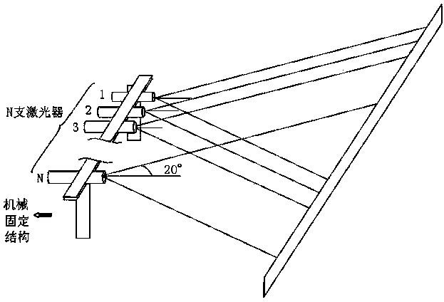
[0010] Such as figure 1 The schematic diagram of the principle of long-range visual navigation based on laser stitching is shown. First, the output spot of a single low-power laser is shaped into a rectangular spot with a required distance through a lens or lens group, and then two or more low-power lasers (with shaping The required lens or lens group) is fixed on the optical table, and through the adjustment of the optical table, the output spots of each laser are overlapped as much as possible, so as to achieve the effect that the light spot intensity distribution of high-power lasers is difficult to achieve. Such as figure 1 shown. The total laser power can be controlled by directly controlling the switch of the low-power laser, so that it can meet the purpose of navigation without causing damage to the human eye within a large distance range and satisfying the visibility of the human eye.

[0011] When only one laser is working at a very short distance, its output power ...


PUM


Abstract

The invention relates to a remote visual navigation method based on laser splicing. The method comprises the following steps: shaping output spots of a single small-power laser into rectangular spots in required distance through a lens or a lens assembly, configuring several small-power lasers with shaping lens or a lens assembly, according to the required power, and finally adjusting an optical platform so that the output spot of each laser coincides within the same range, wherein the several small-power lasers are fixed onto the optical platform rectilinearly. By using the small-power laser replacing a large-power laser, the problem that the lasers meeting the power requirement cannot be found due to high power requirement on the laser by a remote visual navigation system is solved, the problem that the output spots of the large-power laser are poor in quality so as to be difficultly shaped into the rectangular spots meeting the requirement is solved, and the overall laser power can be controlled by directly controlling the small-power laser so as to achieve the purpose of being visible to human eyes under the premise of not harming human eyes within a far distance range, thus realizing the navigation.

Description

technical field [0001] The invention relates to a visual navigation system, in particular to a remote visual navigation method based on laser splicing. Background technique [0002] Compared with other light sources, laser has better directionality, monochromaticity, coherence and higher output power. With the progress and development of modern society, the field of laser application is becoming wider and wider. Visual laser systems are widely used in positioning systems and navigation systems, such as intelligent cruise robots based on GPS-like infrared global positioning systems and monocular vision processing, and vehicle-mounted embedded navigation mark tracking systems based on omnidirectional vision. The visual laser system has the advantages of simple equipment, low cost, fast and accurate positioning, convenient installation and deployment, strong scalability, and easy promotion and application. [0003] For long-range visual navigation systems, in order to achieve...

Claims


Application Information

Patent Timeline
Patent Type & Authority Applications(China)
IPC IPC(8): G01C21/00
CPCG01C21/00
Inventor 王文杰周洪王红陈纪朋贾宏志林旺周伟刘佰滢尤贝王辽
Owner SHANGHAI MARINE EQUIP RES INST
Why Eureka
Try Eureka