Chip type infrared emitter package

An infrared emitter and package technology, which is applied in the direction of electric solid devices, semiconductor devices, electrical components, etc., can solve problems such as uninstructed, and achieve the effect of reducing total heat loss and uniform infrared radiation

Active Publication Date: 2014-08-06
ORIENTAL SYST TECH
View PDF4 Cites 0 Cited by
  • Summary
  • Abstract
  • Description
  • Claims
  • Application Information

AI Technical Summary

Problems solved by technology

Furthermore, said patent does not teach that the pressure in the central cavity has a critical effect on the electro-optical efficiency (representing the efficiency of converting electricity into light energy) of the infrared radiation source

Method used


Image

  • Chip type infrared emitter package
  • Chip type infrared emitter package
  • Chip type infrared emitter package

Examples


Embodiment Construction

[0017] The present invention will be described in detail below in conjunction with the accompanying drawings and embodiments.

[0018] Before the present invention is described in detail, it should be noted that in the following description, similar elements are denoted by the same numerals.

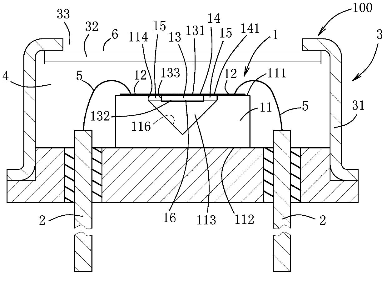
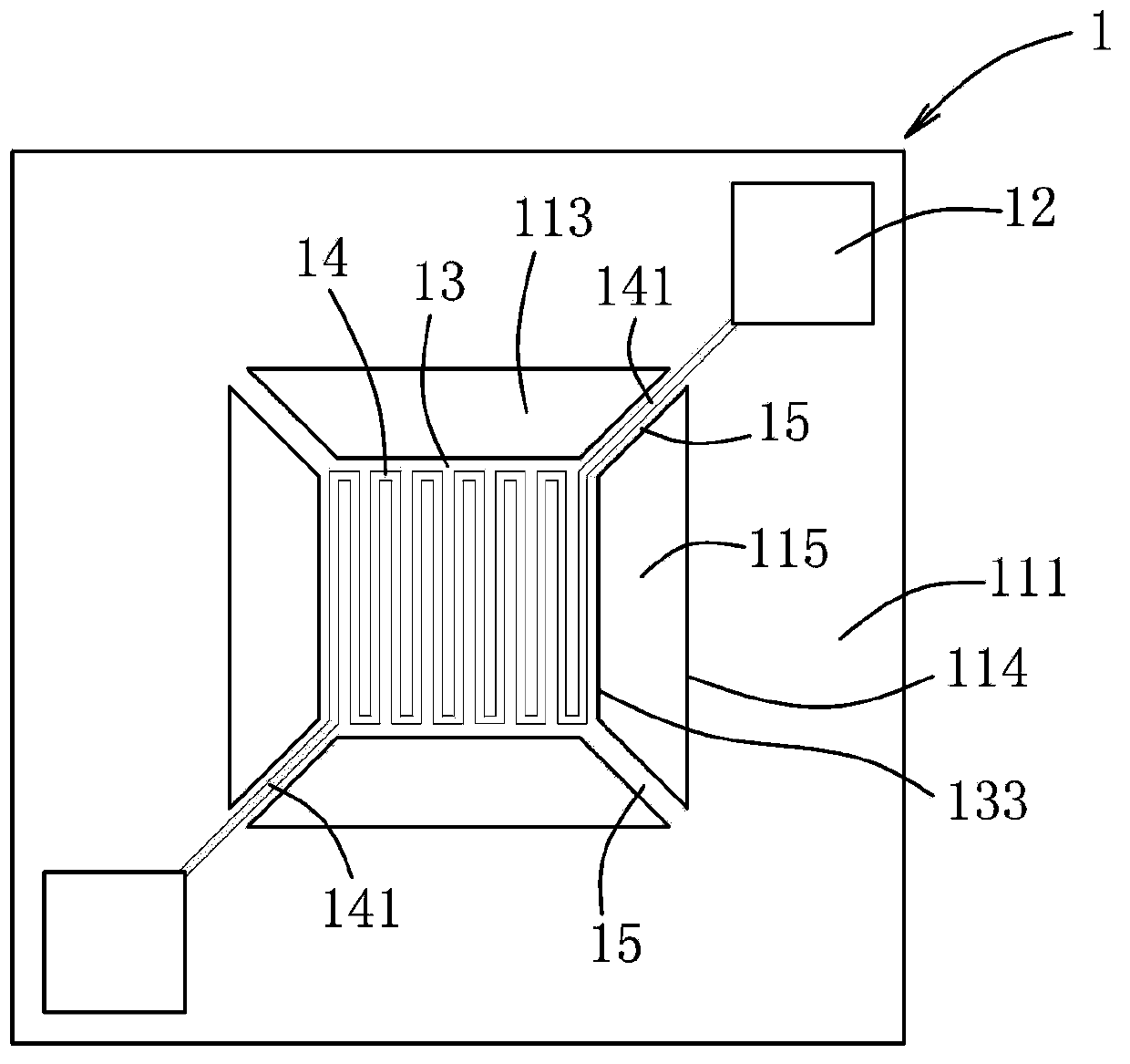
[0019] figure 1 and figure 2 The first preferred embodiment of the chip-type infrared emitter package 100 of the present invention is described.

[0020] The chip-type infrared emitter package 100 includes an emitter chip 1 , a pair of conductive leads 2 and a casing 3 . The transmitter chip 1 includes: a base 11, the base 11 has a top surface 111, a bottom surface 112 and a central cavity 113 extending through the top surface 111, the top surface 111 and the bottom surface 112 are in a Set oppositely in the vertical direction, the central cavity 113 is defined by a cavity defining wall 116, the cavity defining wall 116 has a bottom, and is arranged above the bottom surface 112 of th...


PUM


Abstract

The invention relates to a chip type infrared emitter package, comprising an emitter chip and a shell. The emitter chip comprises a base containing a silicone substrate and having a top surface and a central cavity extending through the top surface, a thin plate having a circumferential end separated from the periphery of the central cavity through a circular gap, a resistor formed on the thin plate and used for heating the thin plate to generate infrared radiation, at least one slimline type beam supporting pin extending to the base from the circumferential end of the thin plate and penetrating through the circular gap so as to suspend the thin plate in the central cavity, thus forming a heat bottleneck of heat conduction from the thin plate to the slimline type beam supporting pin, and a first reflection material covering the bottom surface of the thin plate. The closed vacuum chamber has a pressure lower than 0.01 torr.

Description

technical field [0001] The present invention relates to a chip type infrared emitter package, in particular to a package comprising a thin plate (membrane) suspended on a base (substrate) through a slim supporting beam (slim supporting beam) and a resistor A chip-type infrared emitter package for an electric resistor. Background technique [0002] In the past, incandescent light sources have been used to generate infrared radiation for non-dispersive infrared (NDIR) gas detection. General incandescent light sources include filament bulbs and chip-type infrared emitters. Filament bulbs have disadvantages such as slow thermal response speed and high power consumption (0.6W), so they are not suitable for battery-operated (battery-operated) NDIR gas detection. [0003] U.S. Patent Publication No. 7,989,821 discloses a sealed infrared emitting source made by semiconductor process technology. The infrared emitting source includes a base with a central cavity (central cavity), an...

Claims


Application Information

Patent Timeline
Patent Type & Authority Applications(China)
IPC IPC(8): H01K1/36
CPCH01L2224/48091H01L2924/1461H01L2924/00014H01L2924/00
Inventor 谢正雄黄振堂陈忠男
Owner ORIENTAL SYST TECH
Why Eureka
Try Eureka