Portable device for monitoring state of transformer substation

A technology for monitoring equipment and substations, applied in the field of substation monitoring, can solve problems such as long distances, inability of the monitoring center to understand the on-site inspection situation in time, and the current status of substations cannot be accurately grasped in time, achieving the effect of precise positioning

Inactive Publication Date: 2014-08-06
STATE GRID CORP OF CHINA +1
View PDF7 Cites 5 Cited by
  • Summary
  • Abstract
  • Description
  • Claims
  • Application Information

AI Technical Summary

Problems solved by technology

However, with the substantial increase in the number of substations, the management scope of the operators in the power industry is getting larger and larger. Since there may be dozens of substations under the jurisdiction of the operators on duty at the same time, if the substations are always in the "offline" state, for the current substation If the status cannot be grasped in time and accurately, it will greatly affect the accuracy of judgment and the timeliness of dealing with problems
When the operating personnel go to the site for inspection, due to the long distance, the monitoring center cannot timely understand the on-site inspection situation, and can only wait for the inspection personnel to enter the inspection situation into the system

Method used


Image

  • Portable device for monitoring state of transformer substation
  • Portable device for monitoring state of transformer substation
  • Portable device for monitoring state of transformer substation

Examples


Embodiment Construction

[0017] In order to clearly illustrate the technical features of this solution, the present invention will be described in detail below through specific implementation modes and in conjunction with the accompanying drawings. The following disclosure provides many different embodiments or examples for implementing different structures of the present invention. To simplify the disclosure of the present invention, components and arrangements of specific examples are described below. Furthermore, the present invention may repeat reference numerals and / or letters in different instances. This repetition is for the purpose of simplicity and clarity and does not in itself indicate a relationship between the various embodiments and / or arrangements discussed. It should be noted that components illustrated in the figures are not necessarily drawn to scale. Descriptions of well-known components and processing techniques and processes are omitted herein to avoid unnecessarily limiting the...


PUM


Abstract

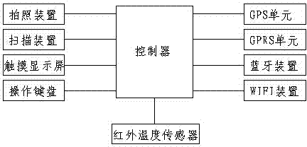
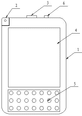
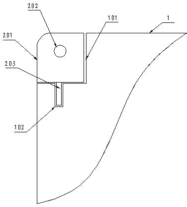
The invention discloses a portable device for monitoring state of a transformer substation. The portable device comprises a shell, a controller, a photographing device, a scanning device, a touch display screen, an operation keyboard, a GPS (Global Position System) unit, a GPRS (General Packet Radio Service) unit, a Bluetooth device and a WIFI (Wireless Fidelity) device, wherein the controller is arranged in the shell; the photographing device comprises a rotation block, a camera and a hollow rotation shaft; the rotation block is arranged on the shell; the camera is fixed on the rotation block; one end of the hollow rotation shaft is connected to the rotation block; a groove for containing the rotation block is formed in the shell; a cylindrical cavity for containing the hollow rotation shaft is formed in the bottom of the groove. By virtue of the GPRS unit or the WIFI device and a dispatching automation system, data is transmitted, so that state information and action information of the transformer substation can be obtained from the dispatching automation system in real time, and thus operation state information of the dispatching automation system can be known in time; meanwhile, the GPRS unit is used for sending inspection situation to a monitoring center in real time.

Description

technical field [0001] The invention relates to a substation monitoring device, in particular to a portable substation state monitoring device, which belongs to the technical field of substation monitoring. Background technique [0002] With the development of smart grid, monitoring and analyzing the status of equipment in substations has become a very important part. However, with the substantial increase in the number of substations, the management scope of the operators in the power industry is getting larger and larger. Since there may be dozens of substations under the jurisdiction of the operators on duty at the same time, if the substations are always in the "offline" state, for the current substation If the status cannot be grasped in time and accurately, it will greatly affect the accuracy of judgment and the timeliness of dealing with problems. When the operating personnel go to the site for inspection, due to the long distance, the monitoring center cannot timely...

Claims


Application Information

Patent Timeline
Patent Type & Authority Applications(China)
IPC IPC(8): H02J13/00
CPCY04S10/40
Inventor 王佳科张利民明志舒张成张福友李小英亓超黄义波刘志强
Owner STATE GRID CORP OF CHINA
Why Eureka
Try Eureka