Automatic generating and charging energy-saving system for new energy electric vehicle and manufacturing method thereof

An automatic power generation and energy-saving system technology, applied in the field of electric vehicles, can solve the problems of short battery life, high overall cost, and poor safety

Inactive Publication Date: 2014-08-13
董国良
7 Cites 4 Cited by

AI-Extracted Technical Summary

Problems solved by technology

[0003] The existing electric vehicle technology uses lead-acid batteries or other types of batteries as the main source of driving force. It needs to be charged once a day (6-8 hours) to continue driving for 120-160 kilometers, and the battery life is short. High cost, poor safety, rear wheel d...

Method used

7), leakage protector 15 is installed on the total con...

Abstract

The invention discloses an automatic generating and charging energy-saving system for a new energy electric vehicle. The automatic generating and charging energy-saving system is characterized by comprising a generator, a voltage stabilizing regulator, a charger, a frequency converter, a driving motor, a speed changer, a battery pack, a starting motor, a driving belt, a fan, belt wheels, a master control panel, wires and a base plate, wherein the generator is connected with the voltage stabilizing regulator by one wire and is positioned at the rear end of the generator; the voltage stabilizing regulator is connected with the frequency converter by the wire; the frequency converter is connected with the driving motor by one wire; the charger is connected with the battery pack by one wire; the battery pack is connected with the starting motor by one wire; the starting motor and the generator are both fixedly arranged on the base plate; the belt wheels are arranged on rotating shafts of the starting motor and the generator respectively and are connected with the generator by the driving belt; the fan is connected to one end of the rotating shaft of the generator; the starting motor drives the generator to start. The automatic generating and charging energy-saving system has the advantages that the battery pack is charged by utilizing electric quantity left during the power generation of the generator, and the battery pack is directly used for supplying power to the starting motor to implement the automatic generating and charging functions.

Application Domain

Vehicular energy storageElectric energy management +1

Technology Topic

Residual chargeElectric generator +12

Image

  • Automatic generating and charging energy-saving system for new energy electric vehicle and manufacturing method thereof

Examples

  • Experimental program(1)

Example Embodiment

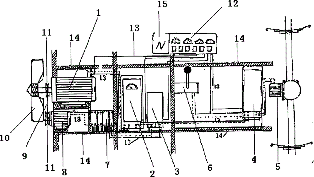
[0024] The present invention will be further described below in conjunction with the accompanying drawings:
[0025] like figure 1 As shown, the technical solution adopted in the present invention is as follows: a new energy electric vehicle automatic power generation, charging and energy-saving system, characterized in that it includes a generator 1, a voltage regulator 2, a charger 3, a frequency converter 4, a drive motor 5, Transmission 6, battery pack 7, starter motor 8, drive belt 9, fan 10, pulley 11, master control panel 12, wire 13, chassis 14, generator 1 is connected to voltage regulator 2 through wire 13 and is located behind generator 1 The voltage regulator 2 is connected to the inverter 4 through the wire 13, the inverter 4 is connected to the drive motor 5 through the wire 13, the charger 3 is connected to the battery pack 7 through the wire 13, and the battery pack 7 is connected to the starter motor 8 through the wire 13. Both the starter motor 8 and the generator 1 are fixedly arranged on the chassis 14, and pulleys 11 are respectively provided on the rotating shafts of the two. The two pulleys 11 are connected to the generator 1 through the transmission belt 9, and the fan 10 is connected to one end of the rotating shaft of the generator 1. The starter motor 8 drives the generator 1 to start.
[0026] The power line of the charger 3 is connected to the output line of the voltage regulator regulator 2 .
[0027] The drive motor 5 is fixed on the chassis 14, the drive motor 5 is connected to the frequency converter 4, and the drive motor 5 converts electrical energy into mechanical energy to drive the electric vehicle to move; .
[0028] The general control panel 12 is provided with a leakage protector 15, and the general control panel 12 is connected to the generator 1, the voltage regulator 2, the charger 3, the frequency converter 4, the drive motor 5, the transmission 6, the battery pack 7, Start the motor 8-phase connection.
[0029] The described energy-saving system for automatic power generation, charging, and production of a new energy electric vehicle and a method for making the same are characterized by comprising the following steps:
[0030] 1), the design vehicle chassis 14 is connected with the above-mentioned components;
[0031] 2), design the connection position of generator 1 and starter motor 8;
[0032] 3), design the voltage regulator regulator 2 to adjust the voltage and current issued by the generator 1;
[0033] 4), design the drive motor 5, the power supply of the drive motor 5 is the power supply from the generator 1;
[0034] 5), design the charger 3 to quickly charge the battery pack 7;
[0035] 6), the design utilizes the frequency converter 6 to control the rotational speed of the drive motor 5;
[0036] 7), a leakage protector 15 is installed on the main control panel 12 to prevent leakage of each component;
[0037] 8), the overall control panel 12 is designed to be connected and controlled with the above components;
[0038] 9) Design the electric vehicle to start and run normally in various environments;
[0039] 10) Assemble the above components.
[0040] Further, the electric energy generated by the generator 1 is used as the main power source for driving the motor 5. The rotational power of the generator 1 comes from the starter motor 8 and the wind power, and the energy of the starter motor 8 comes from the battery pack 7. The rate is greater than the power of the drive motor 5 .
[0041] Further, the voltage regulator 2 controls the stability and regulation of the output power, and the sent current controls the operation of the drive motor 5 through the inverter 4; automatic conversion, when the car runs above 30 km/h, the wind power will be reduced. It can generate electricity, start the motor 8 to automatically stop working, and realize automatic conversion to generate electricity, which can increase the service life of the battery pack, and set up multiple leakage protectors and a master control panel to automatically control the above parts.
[0042] Further, the battery pack 7 is connected to the starter motor 8 through the wire 13; the generator 1 is connected to the voltage regulator 2 through the wire 13; .
[0043] The embodiments of the present invention merely describe the specific implementations thereof, and are not intended to limit the protection scope thereof. Those skilled in the art can make some modifications under the inspiration of this embodiment, so all equivalent changes or modifications made according to the scope of the patent of the present invention are all within the scope of the claims of the patent of the present invention.

PUM

no PUM

Description & Claims & Application Information

We can also present the details of the Description, Claims and Application information to help users get a comprehensive understanding of the technical details of the patent, such as background art, summary of invention, brief description of drawings, description of embodiments, and other original content. On the other hand, users can also determine the specific scope of protection of the technology through the list of claims; as well as understand the changes in the life cycle of the technology with the presentation of the patent timeline. Login to view more.
Why Eureka
Try Eureka