Filter element replacing device and method and fresh air fan

A new fan and filter element technology, applied in the field of filter element replacement devices, can solve the problems of unfavorable conventional installation of filter element replacement devices, lack of hidden storage of filter elements, lack of positioning accuracy and smoothness, etc., and achieve the goal of reducing the number of manual replacement and cleaning of filter elements Effect

Active Publication Date: 2014-08-13
GREE ELECTRIC APPLIANCES INC
View PDF3 Cites 30 Cited by
  • Summary
  • Abstract
  • Description
  • Claims
  • Application Information

AI Technical Summary

Problems solved by technology

[0004] 1. Lack of hidden storage for the used filter element, which is easy to cause secondary pollution of the unused filter element by the pollution particles on the filter element;
[0005] 2. The positioning accuracy and smoothness of the movement are lacking;
[0006] 3. The internal space of the main unit of the fresh air blower is small, while the movement mechanism of the filter element replacement device takes up a large space, which is not conducive to the conventional installation of the movement mechanism of the filter element replacement device, and limits the size of the replaceable filter element

Method used


Image

  • Filter element replacing device and method and fresh air fan
  • Filter element replacing device and method and fresh air fan
  • Filter element replacing device and method and fresh air fan

Examples


Embodiment Construction

[0038] The technical solutions of the present invention will be described in further detail below with reference to the accompanying drawings and embodiments.

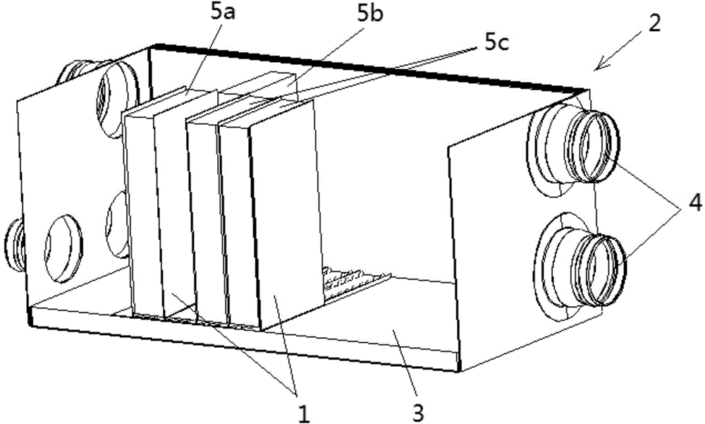
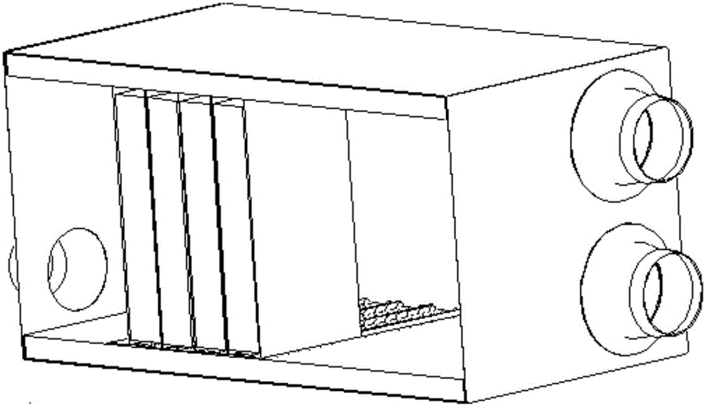
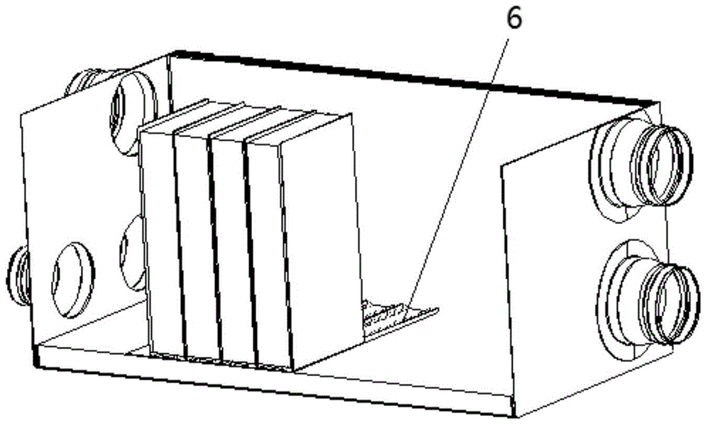
[0039] Such as figure 1 As shown, it is a schematic structural diagram of an embodiment of the filter element replacement device of the present invention. In this embodiment, the filter element replacement device mainly includes two mechanisms, namely a filter element storage mechanism and a power supply mechanism. Wherein, the filter element storage mechanism can accommodate at least two filter elements, providing a storage area for the new filter element before replacement and the old filter element after replacement. From figure 1 As can be seen in the figure, the filter element storage mechanism includes a plurality of partitions 1 whose size is not smaller than the filter element. Here it is required that the size of the separator should not be smaller than the filter element, so that the separator can completel...


PUM


Abstract

The invention relates to a filter element replacing device and method and a fresh air fan. The device comprises a filter element storage mechanism capable of accommodating at least two filter elements, and a power supply mechanism for driving a new filter element from the filter element storage mechanism to a working position and driving a filter element to be replaced to retract from the working position to the filter element storage mechanism. The filter element storage mechanism comprises a plurality of partition boards which are not smaller than the filter elements in size, and the partition boards enclose accommodating areas for accommodating the filter elements and separate the neighboring filter elements from one another. According to the filter element replacing device, the partition boards enclose the accommodating areas for accommodating the new filter elements and the old filter elements and separate the neighboring filter elements from one another, so that secondary pollution of pollutant particles on the old filter elements to the new filter elements due to the fact that the new filter elements and the old filter elements move close to each other; the power supply mechanism can convey the unused new filter element to the working position for performing air filtering operation and meanwhile convey the old filter element to be replaced back to the filter element storage mechanism for storage, so that the number of times for manual replacement and filter element cleaning can be reduced, and users can be worry-free and relieved.

Description

technical field [0001] The invention relates to fresh air blower technology, in particular to a filter element replacement device and method and a fresh air blower. Background technique [0002] For a traditional fresh air fan, the filter element for filtering air (hereinafter referred to as the filter element) is usually fixed at a certain position inside the fresh air fan. The filter element is a consumable part that needs to be manually cleaned or replaced regularly. Its service life is generally 3 to 6 months. If it is located in an area with serious air pollution, the replacement of the filter element will be more frequent, which will bring great harm to the user. A certain amount of trouble has come, especially for ceiling-mounted fresh air fans, whose frequent replacement of filter elements makes users feel even more inconvenient. [0003] In order to solve this problem, there has been a solution to automatically replace the filter element in the new fan, which can d...

Claims


Application Information

Patent Timeline
Patent Type & Authority Applications(China)
IPC IPC(8): F24F13/28F24F3/16
Inventor 李绍斌谭建明杜辉刘煜詹朝永刘莹苏炳珲
Owner GREE ELECTRIC APPLIANCES INC
Why Eureka
Try Eureka