On-line continuous concentration detection device for printing and dyeing process liquid

A printing and dyeing process and concentration detection technology, which is applied to measuring devices, instruments, scientific instruments, etc., can solve problems such as changes in detection accuracy, changes in process liquid density, blockage of process liquid circulation pipes, and achieve constant speed and high concentration detection accuracy , the effect of easy maintenance

Active Publication Date: 2016-03-02
常州宏大智慧科技有限公司
View PDF9 Cites 0 Cited by
  • Summary
  • Abstract
  • Description
  • Claims
  • Application Information

AI Technical Summary

Problems solved by technology

[0010] . Due to the large content of additives such as slurry and enzyme in the process liquid, if the flow rate of the process liquid is low, it is easy to cause blockage of the process liquid circulation pipeline;
[0011] . Due to certain changes in the temperature of the process liquid in the working tank, the density of the process liquid will change, which will also lead to changes in the detection accuracy.

Method used


Image

  • On-line continuous concentration detection device for printing and dyeing process liquid
  • On-line continuous concentration detection device for printing and dyeing process liquid
  • On-line continuous concentration detection device for printing and dyeing process liquid

Examples


Embodiment 1

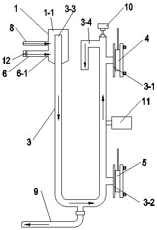
[0038] like figure 1 As shown, an online continuous concentration detection device for printing and dyeing process liquid, including a process liquid buffer container 1, a detection flow pipe 3, a first pressure sensor 4, a second pressure sensor 5 and a liquid inlet pipe 6;

[0039] One end of the liquid inlet pipe 6 communicates with the process liquid buffer container 1;

[0040] One end of the detection flow pipe 3 communicates with the process liquid buffer container 1, and one end of the detection flow pipe 3 is the process liquid circulation inlet 3-3, and the height of the process liquid flow inlet 3-3 is lower than the process liquid buffer container 1 The height of the upper overflow port 1-1; the upper overflow port 1-1 can be as figure 1 The upward opening on the upper top of the process liquid buffer container 1 as shown may also be a gap or an overflow hole or an overflow nozzle on the side wall of the upper part of the process liquid buffer container 1 in the...

Embodiment 2

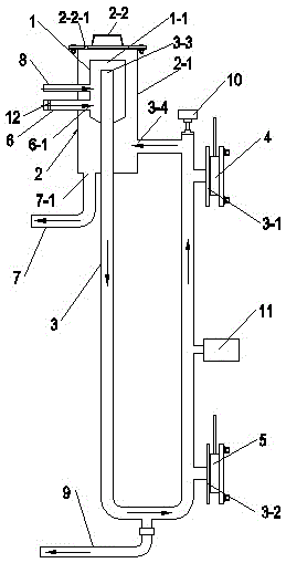
[0048] like figure 2 As shown, the difference between embodiment 2 and embodiment 1 is: an online continuous concentration detection device for printing and dyeing process liquid, which also includes a process liquid recovery container 2, and the process liquid recovery container 2 has a liquid outlet 7-1, And the height of the liquid outlet 7 - 1 of the process liquid recovery container 2 is lower than the height of the upper overflow port 1 - 1 of the process liquid buffer container 1 . In this way, in order to facilitate the recovery of process liquid.

[0049] like figure 2 As shown, the process liquid buffer container 1 is arranged in the process liquid recovery container 2; one end of the liquid inlet pipe 6 penetrates the process liquid recovery container 2 and is connected with the process liquid buffer container 1; the detection flow pipe One end of 3 passes through the bottom of the process liquid recovery container 2 and the bottom of the process liquid buffer c...

Embodiment 3

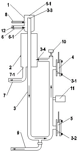
[0055] like image 3 As shown, the difference between embodiment 3 and embodiment 2 is: an online continuous concentration detection device for printing and dyeing process liquid, the process liquid buffer container 1 is arranged above the process liquid recovery container 2, and the process liquid recovery container 2 includes the container body only. Other structures of embodiment 3 are exactly the same as embodiment 2.


PUM


Abstract

The invention relates to an on-line continuous dyeing and printing process liquid concentration detection device which comprises a process liquid buffer container, a detection runner pipe, a first pressure sensor, a second pressure sensor and a liquid inlet pipe, wherein one end of the liquid inlet pipe is communicated with the process liquid buffer container; one end of the detection runner pipe is communicated with the process liquid buffer container; one end of the detection runner pipe is provided with a process liquid circulation inlet; the height of the process liquid circulation inlet is lower than the height of an upper overflow hole of the process liquid buffer container; a process liquid circulation outlet is formed in the detection runner pipe; the process liquid circulation inlet of the detection runner pipe is higher than the process liquid circulation outlet; the first pressure sensor and the second pressure sensor are vertically separated from each other and are respectively connected with the detection runner pipe. According to the device, the flow velocity of process liquid can be constant, the detection accuracy is high, and the device is convenient to maintain.

Description

technical field [0001] The invention relates to a concentration detection device, in particular to an online continuous concentration detection device for printing and dyeing process liquid. Background technique [0002] At present, in the printing and dyeing mercerizing process, the concentration of alkali in the process solution is controlled manually, that is, the alkali solution with the required concentration is prepared by manual titration. During the operation of the equipment, after the fabric passes through the lye, the concentration of alkali in the lye will naturally decrease due to the adsorption of the fabric. In order to maintain the concentration of alkali in the lye, a certain concentration of concentrated alkali must be manually added to the process solution. In order to maintain the concentration of alkali in the process solution. However, this method is not a real-time and continuous process, and the concentration of lye is very unstable, which may easily...

Claims


Application Information

Patent Timeline
Patent Type & Authority Patents(China)
IPC IPC(8): G01N33/00
Inventor 顾金华
Owner 常州宏大智慧科技有限公司
Why Eureka
Try Eureka