Indicating instrument detecting system and method

A technology for indicating instruments and detection systems, which is applied in the direction of instruments, measuring devices, and measuring electrical variables. It can solve the problems of difficult to read accurately, no communication interface, and large data volume, so as to improve detection efficiency, avoid manual operation, and reduce system costs. effect of error

Inactive Publication Date: 2014-08-13
STATE GRID CORP OF CHINA +1
View PDF8 Cites 3 Cited by
  • Summary
  • Abstract
  • Description
  • Claims
  • Application Information

AI Technical Summary

Problems solved by technology

However, because the data acquisition of common indicating instruments is mostly carried out by manual reading, there are problems such as large errors, difficult to read accurately, and no communication interface, etc., and because of the limitations of testing equipment and testing methods, it is difficult for the development of measurement work. It has a great impact, and it is also not conducive to the safe and stable operation of the power grid.
Moreover, due to the rich test types, large amount of data, and poor manual operation accuracy in practical app

Method used


Image

  • Indicating instrument detecting system and method
  • Indicating instrument detecting system and method
  • Indicating instrument detecting system and method

Examples


Example Embodiment

[0019] The technical solutions in the embodiments of the present invention will be clearly and completely described below in conjunction with the accompanying drawings in the embodiments of the present invention. Obviously, the described embodiments are only a part of the embodiments of the present invention, rather than all the embodiments. Based on the embodiments of the present invention, all other embodiments obtained by those of ordinary skill in the art without creative work shall fall within the protection scope of the present invention.

[0020] The embodiment of the present invention provides an indicating instrument detection system and method. The present invention will be described in detail below with reference to the drawings.

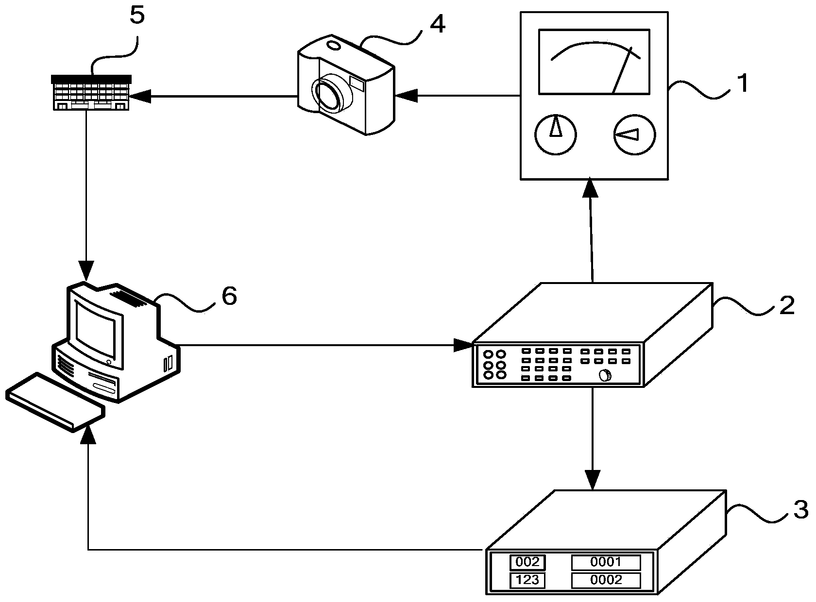
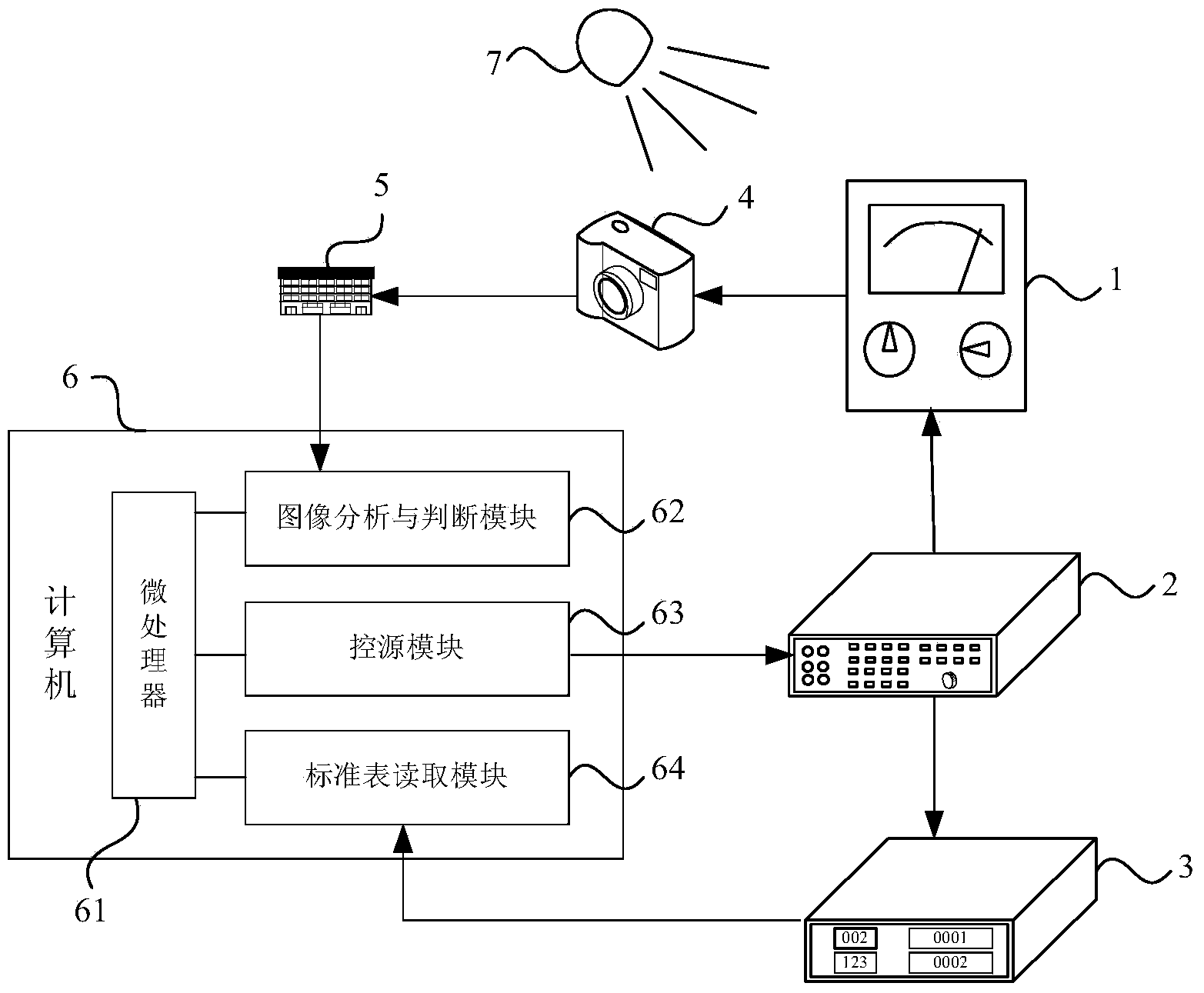
[0021] Such as figure 1 As shown, the indicating instrument detection system includes: the measured indicating instrument 1, the standard source 2, the standard meter 3, the CMOS camera 4, the data acquisition card 5 and the computer 6.

[0022...


PUM


Abstract

The invention provides an indicating instrument detecting system and method. The detecting system comprises a detected indicating instrument, a standard source, a standard meter, a CMOS camera, a data acquisition card and a computer, wherein the standard source is connected with the detected indicating instrument, the standard meter and the computer, the CMOS camera is connected with the data acquisition card, and the data acquisition card is inserted into a card slot of the computer; the standard source outputs testing benchmark electricity quantity to the detected indicating instrument and the standard meter according to a testing benchmark value; the standard meter outputs a standard value generated according to the testing benchmark electricity quantity to the computer; the CMOS camera acquires an image of the dial plate of the detected indicating instrument in real time, and the image of the dial plate is transmitted to the computer through the data acquisition card; when a pointer in the image of the dial plate coincides with a scale value corresponding to the testing benchmark value, the computer sends a stopping instruction to the standard source, and a current standard value output by the standard meter to the computer is recorded; whether error exceeds an error standard value or not is judged by the computer according to the current standard value and the testing benchmark value, and a judgment result is output.

Description

Technical field [0001] The present invention relates to an indicating instrument detection technology, in particular to an indicating instrument detection method and system. Background technique [0002] In the process of detecting whether the grid system is operating normally, the indicating instrument is widely used because of its analog circuit design which can accurately monitor the electricity. However, because the data acquisition of common indicating instruments mostly uses manual readings for instrument detection, there are problems such as large errors, difficult readings, and no communication interface. Also, due to the limitations of detection equipment and detection methods, the measurement work is carried out. Bringing a greater impact, but also not conducive to the safe and stable operation of the power grid. In addition, due to the abundant test types, large amount of data, and poor manual operation accuracy in practical applications, it is difficult to improve th...

Claims


Application Information

Patent Timeline
IPC IPC(8): G01R35/00
Inventor 丁恒春王晓燕周丽霞徐占河杨晓波张春雪赵晶李亭
Owner STATE GRID CORP OF CHINA
Why Eureka
Try Eureka