Mixed-mode cavity filter

一种腔体滤波器、复合模式的技术,应用在波导型器件、电气元件、电路等方向,能够解决损耗高、尺寸大、费用高等问题,达到损耗低的效果

Inactive Publication Date: 2014-08-13
ACE TECH
View PDF3 Cites 8 Cited by
  • Summary
  • Abstract
  • Description
  • Claims
  • Application Information

AI Technical Summary

Problems solved by technology

[0005] Dielectric resonators can ensure low loss, but they are large in size and expensive, while metal coaxial resonators can ensure light weight and miniaturization of filters, but they have high losses

Method used


Image

  • Mixed-mode cavity filter
  • Mixed-mode cavity filter
  • Mixed-mode cavity filter

Examples


Embodiment Construction

[0028] Although the present invention can be modified variously and has a plurality of embodiments, specific embodiments are illustrated in the drawings and described in detail. However, this is not intended to limit the present invention to specific embodiments, and it should be understood that all changes, equivalents, and substitutions included in the spirit and technical scope of the present invention are included. When describing each drawing, similar reference numerals are used for similar components.

[0029] Hereinafter, embodiments of the present invention will be described in detail with reference to the drawings.

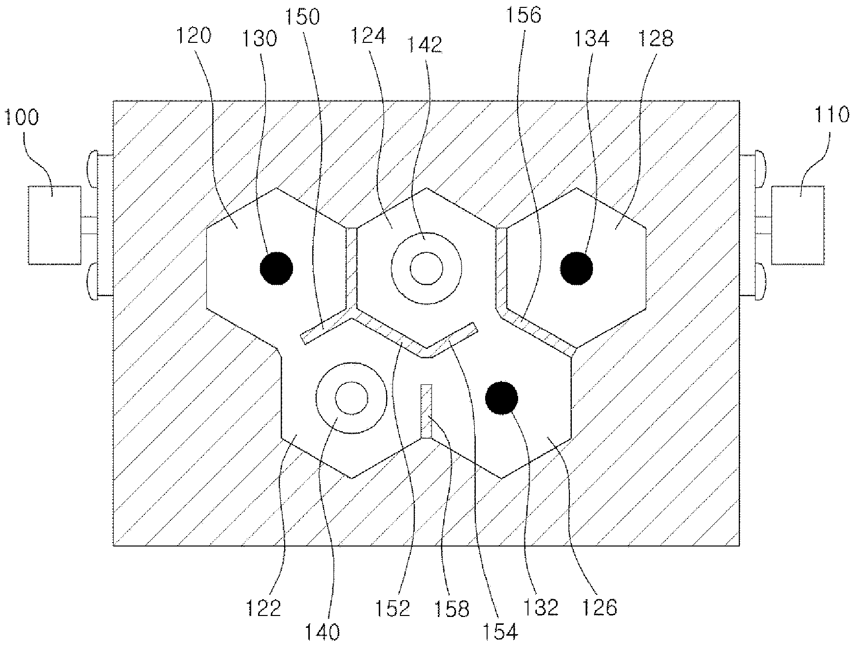
[0030] figure 1 It is a plan view of the composite mode cavity (Cavity) filter in the first embodiment of the present invention after removing the outer cover.

[0031] Such as figure 1 As shown, the composite mode cavity filter of the first embodiment of the present invention includes an input port 100, an output port 110, a plurality of cavities 120,...


PUM


Abstract

A mixed-mode cavity filter is disclosed. The disclosed cavity filter includes: at least one first cavity configured to hold a metal coaxial resonator; and at least one second cavity configured to hold a dielectric resonator, where a first coupling window is formed in a wall formed between the first cavity and the second cavity, the first coupling window includes a horizontal window formed parallel to a bottom portion and a vertical window formed perpendicularly to the bottom portion, and the horizontal window and the vertical window overlap each other in at least a partial area. A mixed-mode filter according to an embodiment of the invention can achieve a small size and a light weight while providing low losses.

Description

technical field [0001] Embodiments of the present invention relate to a cavity filter, in particular to a composite mode cavity filter in which different modes are combined. Background technique [0002] With the rapid development of communication services, the speed of data transmission is increasing. For this reason, it is necessary to increase the system bandwidth, improve the sensitivity of information reception, and minimize the interference caused by other communication system carriers. [0003] Therefore, the demand for broadband filters with low loss (Low insertion loss) and high rejection (High rejection) is increasing day by day. In addition, in order to prevent the loss of transmission power and the decrease of information receiving sensitivity caused by the feeder cable of the base station, all radio frequency (RF: Radio Frequency) units are set at the bottom of the base station antenna, such as the tower mounted amplifier (TMA: Tower Mounted Amplifier ), wirele...

Claims


Application Information

Patent Timeline
Patent Type & Authority Applications(China)
IPC IPC(8): H01P1/208
CPCH01P1/2053H01P1/2084H01P1/2086H01P1/20
Inventor 千东完张宰原徐在玉
Owner ACE TECH
Why Eureka
Try Eureka