Power electronic transformer control method and system

A technology of power electronics and control methods, applied in the direction of control/regulation systems, regulation of electrical variables, instruments, etc., can solve problems such as system collapse, complex control algorithms, voltage imbalance, etc., and achieve the effect of reducing inrush current

Active Publication Date: 2014-08-13
ELECTRIC POWER RES INST OF GUANGXI POWER GRID CO LTD +1
View PDF3 Cites 16 Cited by
  • Summary
  • Abstract
  • Description
  • Claims
  • Application Information

AI Technical Summary

Problems solved by technology

[0004] However, once the control system of the DC microgrid’s multi-agent system (Multi Agent System, MAS) loses control or the communication command fails, it will lead to voltage imbalance or even system collapse; and the control algorithm is quite complicated, which increases the difficulty

Method used


Image

  • Power electronic transformer control method and system
  • Power electronic transformer control method and system
  • Power electronic transformer control method and system

Examples


Embodiment 1

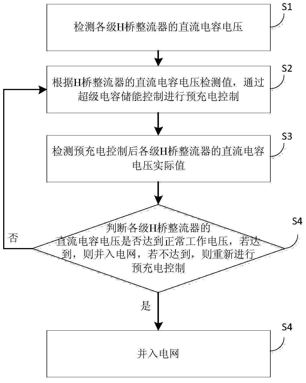
[0053] An embodiment of the present invention provides a control method for power electronic transformer control, see figure 1 , the method includes the following steps:

[0054] S1. Detect the DC capacitor voltages of the H-bridge rectifiers at all levels;

[0055] S2. According to the DC capacitor voltage detection value of the H-bridge rectifier, the pre-charging control is performed through the super capacitor energy storage control;

[0056] S3. Detecting the actual value of the DC capacitor voltage of the H-bridge rectifiers at all levels after the pre-charging control;

[0057] S4. Judging whether the DC capacitor voltages of the H-bridge rectifiers at all levels have reached the normal working voltage, if so, they are connected to the power grid, and if not, the pre-charging control is performed again.

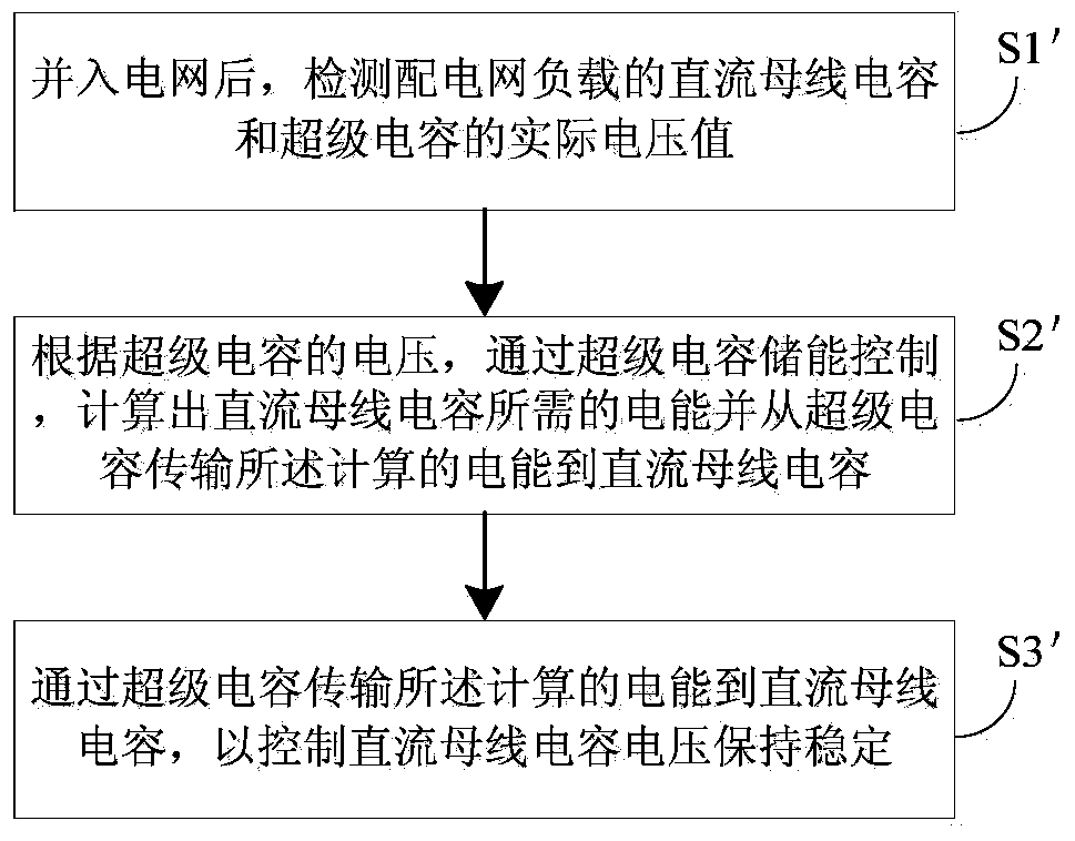
[0058] Optionally, see figure 2 , the method also includes:

[0059] S1'. After being connected to the power grid, detect the actual voltage value of the DC bus cap...

Embodiment 2

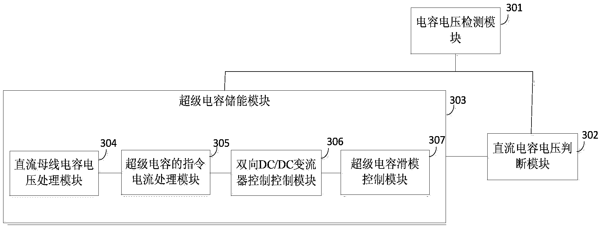
[0075] An embodiment of the present invention provides a power electronic transformer, see image 3 , including the following modules:

[0076] The capacitor voltage detection module 301 is used to detect the DC capacitance of the H-bridge rectifiers at all levels, the DC capacitor voltages of the H-bridge rectifiers at all levels after pre-charging control, the DC bus capacitance of the distribution network load and the actual voltage value of the super capacitor;

[0077] The supercapacitor energy storage module 303 is used to perform pre-charging control through supercapacitor energy storage control according to the actual value of the DC capacitor voltage of the H-bridge rectifier at each level;

[0078] The DC capacitor voltage judging module 302 is used to judge whether the actual value of the DC capacitor voltage of the H-bridge rectifiers at each level reaches the normal working voltage value, and if so, it will be connected to the power grid; if not, the pre-charging ...


PUM


Abstract

The invention provides a power electronic transformer control method and system. The method comprises the following steps: the step S1 in which the direct-current capacitor voltage of each level of H bridge rectifier is detected; the step S2 in which precharging control is performed through supercapacitor energy storage control according to the direct-current capacitor voltage detected values of the H bridge rectifiers; the step S3 in which the direct-current capacitor voltage actual value of each level of H bridge rectifier after precharging control is detected; and the step S4 in which the direct-current capacitor voltage of each level of H bridge rectifier is judged whether to reach the normal working voltage, and if the direct-current capacitor voltage of each level of H bridge rectifier reaches the normal working voltage, then grid connection is performed, and if the direct-current capacitor voltage of each level of H bridge rectifier does not reach the normal working voltage, then precharging control is performed again. The energy storage module of the power electronic transformer of the invention is used to perform precharging control on direct-current bus capacitors before grid connection so as to reduce the impulse current on the switch in the power electronic transformer grid connection process and used to perform charging and discharging control on supercapacitors after grid connection, the direct-current bus voltage is maintained to be in the stable state.

Description

technical field [0001] The invention relates to the field of power electronic control, in particular to a control method and system for a power electronic transformer. Background technique [0002] With the development of high-power power electronic components and their control technology, a new type of transformer, Power Electronic Transformer (PET), which realizes power conversion and energy transfer through power electronic technology, has been increasingly recognized by researchers at home and abroad. more attention. In the field of power electronic control, researchers have proposed a new distributed energy organization and structure - microgrid. Among them, the power electronic transformer provides an interface for various renewable distributed power sources, energy storage devices and loads to be connected to the grid. [0003] In the existing micro-grid technology, the DC micro-grid mostly uses a multi-agent system (Multi Agent System, MAS) to control the DC bus vo...

Claims


Application Information

Patent Timeline
Patent Type & Authority Applications(China)
IPC IPC(8): H02J3/32H02M3/155
Inventor 周柯郑意奉斌许飞涂春鸣刘程辉徐波陈涛吴丽芳欧世峰金庆忍
Owner ELECTRIC POWER RES INST OF GUANGXI POWER GRID CO LTD
Why Eureka
Try Eureka