
Non-contact charging device and non-contact charging method

A non-contact charging device technology, which is applied in the direction of electrical devices, circuit devices, battery circuit devices, etc., can solve the problems of large impact and low efficiency of non-contact charging devices, and achieve the effect of suppressing reflected power

Active Publication Date: 2017-02-15
FUJITSU LTD
View PDF4 Cites 0 Cited by
  • Summary
  • Abstract
  • Description
  • Claims
  • Application Information

AI Technical Summary

Problems solved by technology

Moreover, the efficiency in the non-contact charging device will also be reduced
Especially in the case of high power transmission, the influence is greater

Method used


Image

  • Non-contact charging device and non-contact charging method
  • Non-contact charging device and non-contact charging method
  • Non-contact charging device and non-contact charging method

Examples


Embodiment approach 2

[0099] Embodiment 2 differs from Embodiment 1 in that matching information is not stored in the storage unit 9, but variable information is obtained by calculation.

[0100] Figure 13 It is a diagram showing an example of the operation of the non-contact charging device according to the second embodiment. Steps S131 to S133 , and steps S136 and S137 are the same processes as steps S1 to S3 , steps S6 and S7 described in Embodiment 1, and therefore description thereof will be omitted.

[0101] In step S134, the control unit 8 determines parameters for performing the simulation. For example, various parameters such as the specifications (shape, material, etc.) of the equivalent circuit used in the power transmission and reception system, shields, and the relative positional relationship (distance D1, distance D2, angle θ1) of the power transmission and reception system are input to the electromagnetic field simulator .

[0102] In step S135 , the control unit 8 performs a si...


PUM


Abstract

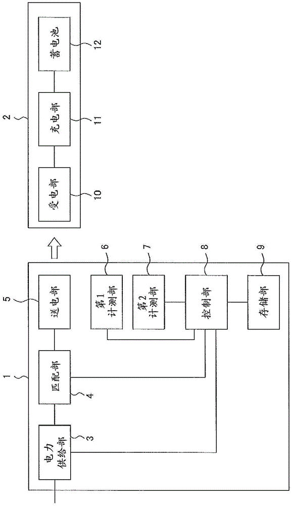
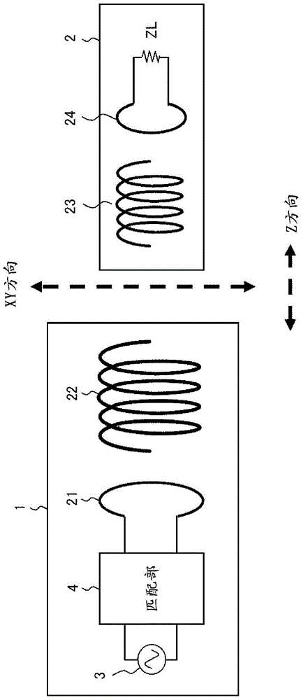
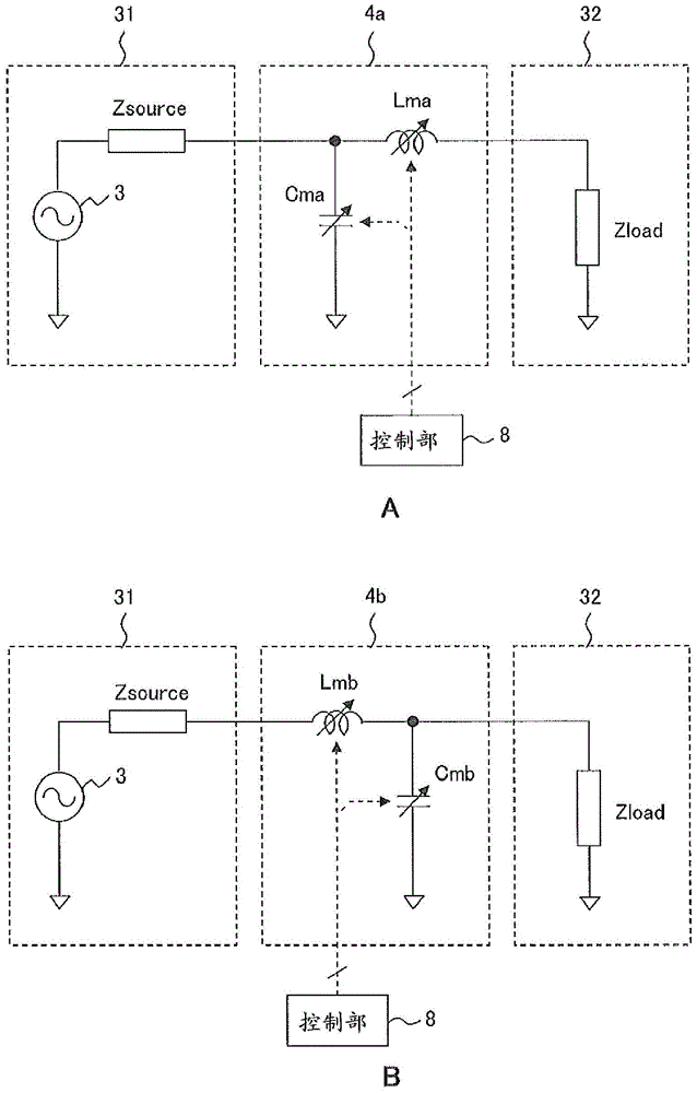
The invention provides a non-contact charging device and a non-contact charging method. The non-contact charging device uses variable information for changing the inductance and capacitance of the matching part associated with the first distance and the second distance, in order to adjust the impedance of the power supply system that supplies AC power and The impedance matching of the power transmission and reception system having the power transmission unit and the power reception device changes the inductance and capacitance of the matching unit, where the first distance represents the distance between the center point of the power transmission resonant coil and the center point of the power reception resonant coil The length of the line segment connecting the positions, the second distance is the distance between the surface having the power transmitting resonant coil and the surface having the power receiving resonant coil, and the matching part is used to make the impedance of the power supply system The impedance matching of the sending and receiving power system varies with the relative position of the electric resonant coil.

Description

technical field [0001] The present invention relates to a non-contact charging device and a non-contact charging method for non-contact charging. Background technique [0002] Conventionally, methods using, for example, electromagnetic induction, electric field coupling, magnetic field resonance, and electric field resonance are known as non-contact charging techniques utilizing an alternating current strong coupling system. Furthermore, in the non-contact charging device used in the above-mentioned non-contact charging technology using the AC strong coupling system, the impedance of the power supply system that supplies the AC power is matched with the impedance of the power transmission unit and the power receiving device (power transmission and reception system). ) determined impedance is essential. That is, when the impedance is not matched, reflected power is generated between the power supply unit and the power transmission unit, thereby affecting the power supply sys...

Claims


Application Information

Patent Timeline
Patent Type & Authority Patents(China)
IPC IPC(8): B60L3/12B60L11/18H02J5/00H02J7/00
CPCH03H7/40B60L3/12B60L2210/30B60L2210/40B60L2270/147Y02T90/12Y02T10/7072Y02T90/14H02J50/90H02J50/12B60L53/122B60L53/126B60L53/305H02J2310/48H02J7/00034Y02T10/70Y02T10/72Y02T90/16H02J50/80B60L53/12B60L53/30H01F38/14H02J50/005
Inventor 内田昭嘉田口雅一松井清人川野浩康下川聪
Owner FUJITSU LTD
Learn More