High-frequency dielectric heating device

A technology of high-frequency induction heating and high-frequency power supply, applied in the direction of dielectric heating, microwave heating, dielectric heating circuit, etc., can solve the problems of low power supply efficiency, high anode voltage, difficult impedance matching, etc., and suppress the damage of power supply , Suppress reflected power, improve the effect of oscillation efficiency

Active Publication Date: 2018-02-16
TOYO SEIKAN GRP HLDG LTD
View PDF10 Cites 17 Cited by
  • Summary
  • Abstract
  • Description
  • Claims
  • Application Information

AI Technical Summary

Problems solved by technology

However, the vacuum tube type high-frequency power supply has the following problems: on the basis of the characteristics of power amplification, its anode voltage is high, and it is large, and the power supply efficiency is low. The cost of the device is increased, and waste heat from the filament is required, and it takes a certain amount of time to start the device. In addition, there is a problem that the resonance frequency changes arbitrarily due to the electrode impedance of the object to be heated.
However, in the configuration in which the third capacitor C3 is a variable-capacitance capacitor and its value is gradually changed, since the electrode impedance also gradually changes accordingly, in particular, the load between the electrodes 30 is like a food material. In the case of such a large capacity and a large change in electrode impedance due to shape, type, heating or thawing temperature, the change will be promoted, making it difficult to perform impedance matching stably
Moreover, in order to maintain the impedance matching in the state where the electrode impedance is unstable, it is necessary to make the first capacitor C1 have a large impedance adjustment range, so that there will be problems that the size of the matching device 40 increases and the cost increases.

Method used


Image

  • High-frequency dielectric heating device
  • High-frequency dielectric heating device
  • High-frequency dielectric heating device

Examples


no. 1 Embodiment

[0062] Next, the first experimental example of the present invention will be explained.

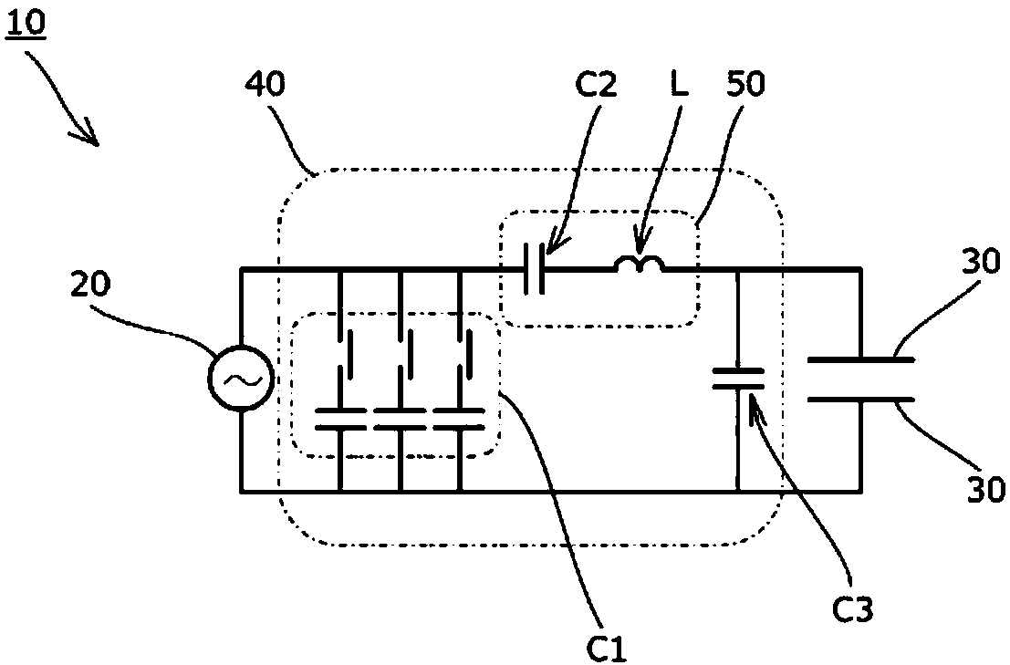
[0063] In the first experimental example, the capacitance of the second capacitor C2 of the reactance circuit 50 was 93 pF, the inductance of the coil L was 1.8 μH, and the impedance of the reactance circuit 50 was adjusted by adjusting the frequency of the high-frequency power source 20. In addition, the capacity of the third capacitor C3 is 400 pF. In addition, the high-frequency power supply 20 is configured to stop the high-frequency output by the protection function when the reflectance detected by the reflected power detection unit exceeds 40%. In addition, as the thawed objects (objects to be heated) arranged between the pair of electrodes 30, frozen persimmons (4 pieces) were used.

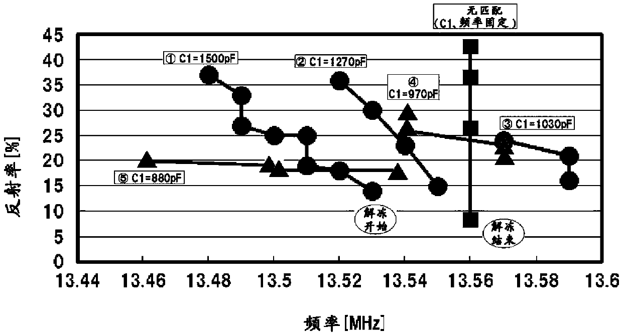
[0064] image 3 Yes: After the defrosting starts, the frequency and reflectance are measured every 1 minute.

[0065] As a case where matching adjustment is not performed with thawing, the capacity of the ...

no. 2 Embodiment

[0080] Next, the second experimental example of the present invention will be explained.

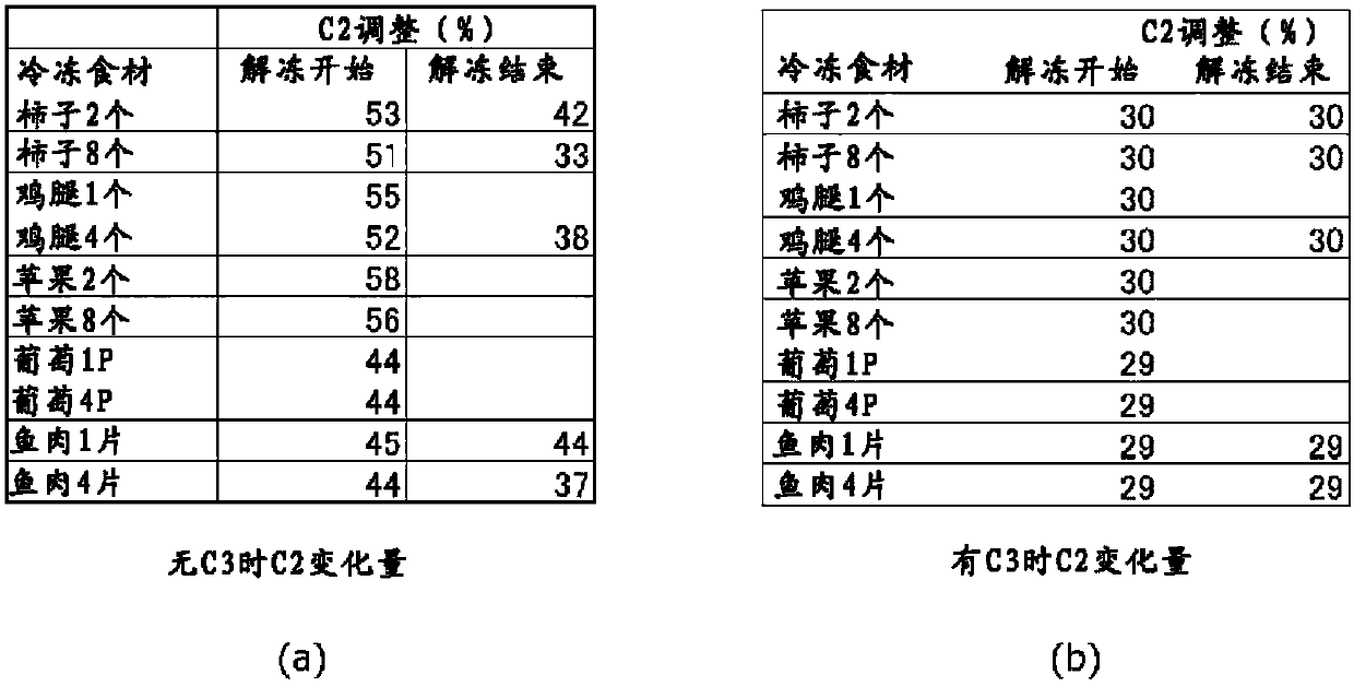
[0081] figure 2 (a) shows the value (capacity%) in the following case, namely: the frequency of the high-frequency power supply 20 = 13.56 MHz, the output impedance of the high-frequency power supply 20 = 50 Ω, the capacity C of the first capacitor C1 1 =1500pF, the capacity C of the second capacitor C2 with variable capacity 2 = 25 to 250 pF, the inductance L of the coil L = 1.8 μH, various ingredients are thawed, and the capacity of the second capacitor C2 is adjusted in order to always minimize the reflected power detected by the reflected power detector.

[0082] When the third capacitor C3 is not connected, the C2 capacity% at the start of thawing varies depending on the type and number of ingredients, and the capacity% of the second capacitor C2 at the end of thawing changes greatly in a decreasing direction. In other words, if the variable width of the capacity of the second capacitor ...


PUM


Abstract

Provided is a high-frequency dielectric heating device for which fine adjustment of inductance is achieved easily and with high precision, while reducing device cost and simplifying device structure.A high-frequency dielectric heating device (10) comprising a high-frequency power source (20), a pair of electrodes (30) disposed facing each other, a reflected power detection means for detecting reflected power occurring due to heating of a substance to be heated, the reflected power detection means being connected between the electrodes (30) and the high-frequency power source (20), and an inductance matching device (40) for adjusting the reflected power, wherein the matching device (40) is provided with a capacitor (C1) connected in parallel to the high-frequency power source (20), and a capacitor (C2) and / or coil (L) with which it is possible to adjust at least reactance, the capacitor (C2) and / or coil (L) being connected in series to the electrodes (30), the high-frequency power source (20) being configured such that frequency can be varied.

Description

Technical field [0001] The present invention relates to a high-frequency induction heating device that uses high-frequency induction heating to heat an object to be heated arranged between facing electrodes, and in particular, to a high-frequency induction heating to defrost frozen food High frequency induction heating device. Background technique [0002] As we all know, in the past, as a high-frequency induction heating device that uses high-frequency induction heating to heat an object to be heated, there are high-frequency induction heating that uses high-frequency induction heating to heat an object to be heated arranged between opposed electrodes. Device (for example, refer to Patent Document 1). The so-called high-frequency induction heating refers to the application of high-frequency voltage to the object to be heated (inductive body), the use of high frequency to change the polarity of the molecules constituting the object to be heated, and the rotation, collision, vibr...

Claims


Application Information

Patent Timeline
Patent Type & Authority Applications(China)
IPC IPC(8): H05B6/50H05B6/64
CPCH05B6/50H05B6/64H05B6/54
Inventor 丸山友树山田真司
Owner TOYO SEIKAN GRP HLDG LTD
Why Eureka
Try Eureka