Method for manufacturing optical fiber grating, optical fiber grating, and fiber laser

a manufacturing method and technology of optical fiber, applied in the field of manufacturing optical fiber grating, optical fiber grating, fiber laser, can solve the problems of insufficient increase of refractive index modulation, difficulty in stably performing laser oscillation at desired oscillation wavelength, blurred refractive index modulation portion, etc., to achieve suppressed heat generation of grating, high oscillation efficiency, and sufficient suppression of reflection wavelength shifts

Active Publication Date: 2013-01-31
THE FUJIKURA CABLE WORKS LTD
View PDF0 Cites 0 Cited by
  • Summary
  • Abstract
  • Description
  • Claims
  • Application Information

AI Technical Summary

Benefits of technology

[0020]According to the aspects of the present invention, in the optical fiber grating, the generation of heat of the grating is suppressed, and the shifts of the reflection wavelength can be sufficiently suppressed. In addition, by using the optical fiber grating, it is possible to obtain an optical component or an optical device such as a fiber laser that has high oscillation efficiency and that can stably perform the laser oscillation.

Problems solved by technology

However, if the periodic refractive index modulation structure portion is lengthened, the reflection wavelength bandwidth of the grating becomes narrow, and thus it is difficult to stably perform the laser oscillation at a desired oscillation wavelength.
However, if the irradiation time of the ultraviolet light is lengthened, due to fluctuation in air or a change in temperature during the irradiation, a minute deviation of the irradiation position of the ultraviolet light in the optical fiber may occur and the refractive index modulation portion may be blurred.
In such a case, there are problems in that the refractive index modulation is not sufficiently increased and an optical fiber grating in which the laser oscillation is stably performed with high oscillation efficiency is not obtained.
However, in the grating that is formed according to the above-described condition, the reflection wavelength is changed when it is used, and there is a problem in that an optical fiber grating is obtained which cannot stably oscillate the laser.

Method used


Image

  • Method for manufacturing optical fiber grating, optical fiber grating, and fiber laser
  • Method for manufacturing optical fiber grating, optical fiber grating, and fiber laser
  • Method for manufacturing optical fiber grating, optical fiber grating, and fiber laser

Examples


example 1

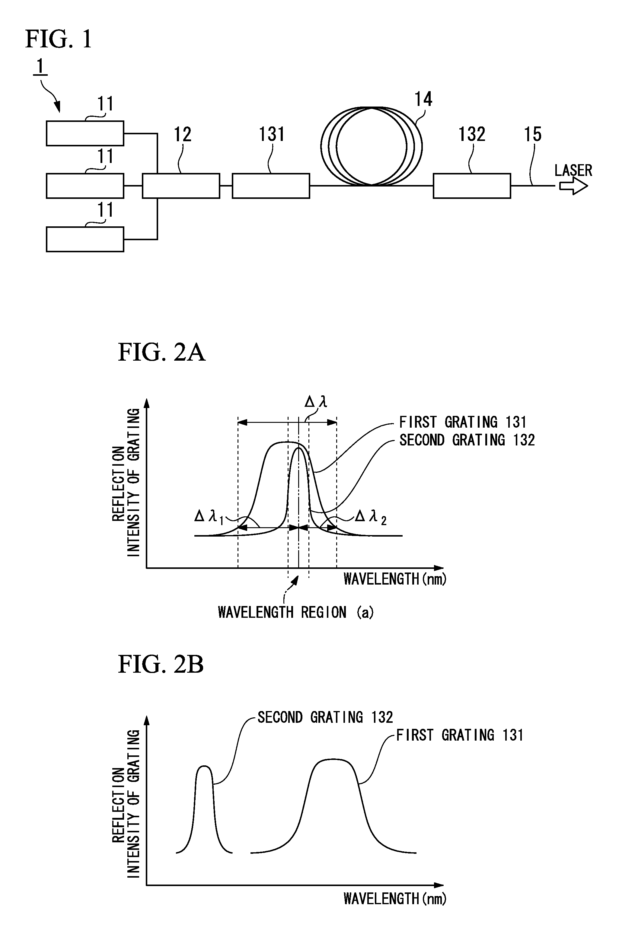
[0113]Considering the possible intensity of the wave-guided light at the time of use, the ultraviolet light was radiated to the optical fiber based on the method according to the above-described embodiment, and a grating having reflectivity of 99% or more and Δλ of 0.1 nm or more was formed. An optical fiber was used which includes a silica glass core doped with GeO2 in a concentration of 2.3 mol % and a silica glass cladding, in which the core diameter is 9 μm, the cladding diameter is 125 μm, the relative refractive index difference (Δ) of the core is 0.23%, and the cutoff wavelength is 945 nm. The optical fiber was hydrotreated at a condition of 300 atmospheric pressure, 50° C., and 100 hours, and thereafter, was subjected to the irradiation of the ultraviolet light. The wavelength of the irradiated ultraviolet light was 248 nm, and the irradiation time was appropriately adjusted so as to obtain the reflectivity of 99% or more.

[0114]In addition, it was implemented at ten differen...

example 2

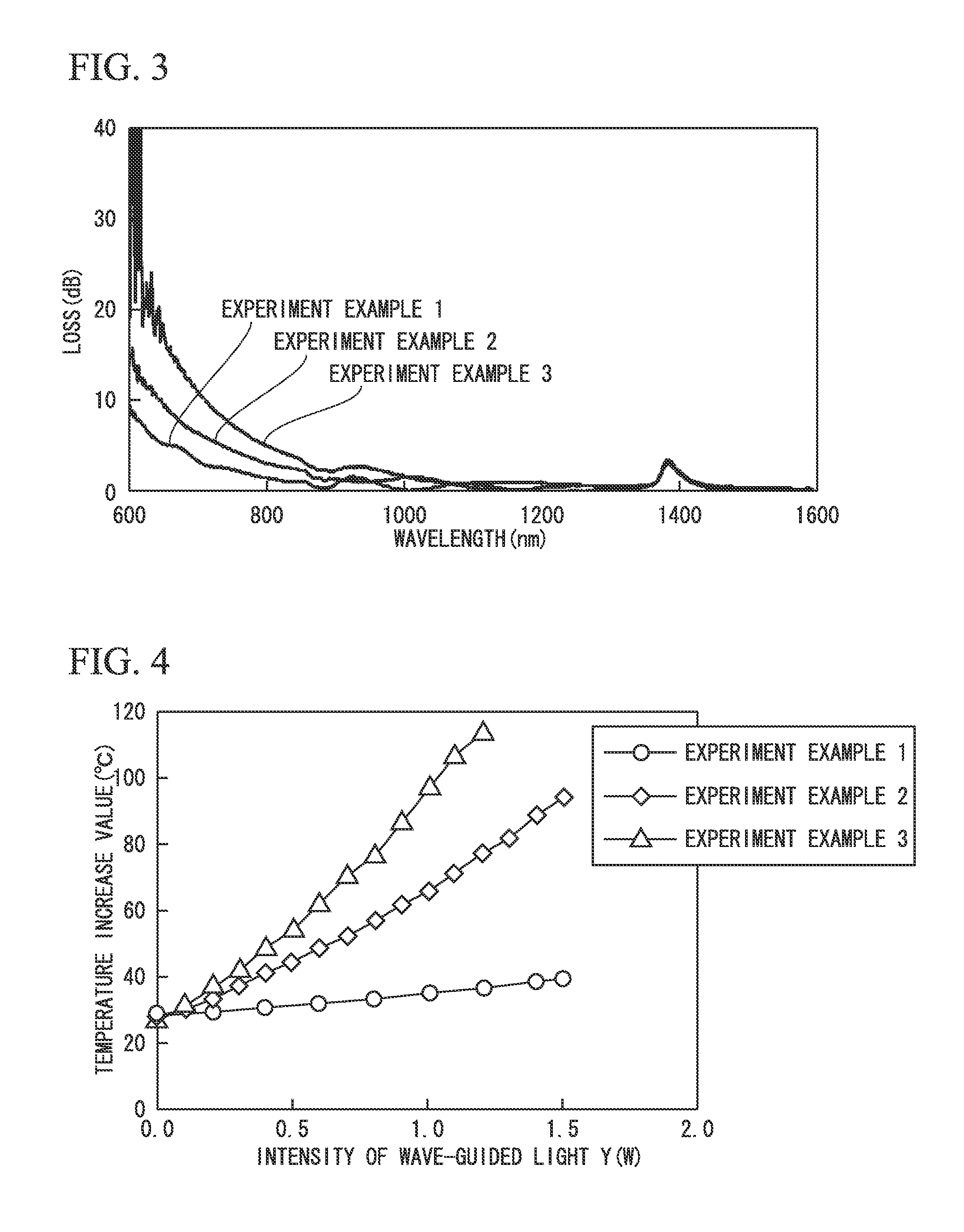
[0118]With respect to the optical fiber grating that was manufactured according to Example 1, a loss spectrum in the grating was measured using a spectrum analyzer while employing white light with wavelengths of 400 to 1800 nm as the wave-guided light. The relationship (absorption characteristic) between the wavelength of the propagated wave-guided light and the loss amount per 1 mm (dB / mm) in the length of the first grating when the wave-guided light was propagated is shown in FIG. 7 for each irradiation intensity of the ultraviolet light when the first grating was formed.

[0119]Moreover, from the results shown in FIG. 7, the relationship between the loss amount per 1 mm (dB / mm) in the length of the first grating when the wave-guided light having wavelengths of 700 nm, 750 nm, and 800 nm was propagated and the irradiation intensity of the ultraviolet light when the first grating was formed was obtained. The results are shown in FIG. 8. The absorption characteristic shown in FIG. 8 s...

example 3

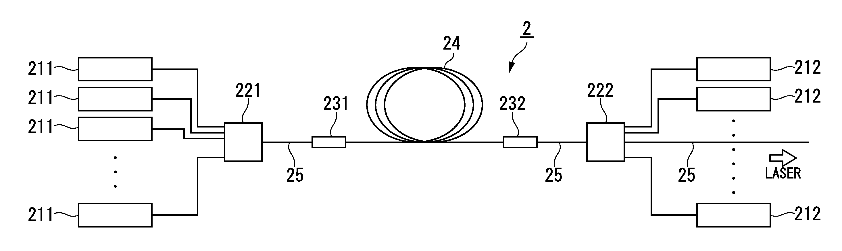
[0121]A first grating was formed using a method in the same way as that of Example 1 except that the irradiation intensity of the ultraviolet light when the grating was formed was set as shown in Table 1, and the fiber laser 2 shown in FIG. 5 including the optical fiber grating was manufactured.

[0122]In the first grating 231, the reflectivity was set to 99.5% and Δλ was set to 0.5 nm. In the second grating 232, the reflectivity was set to 10% and Δλ was set to 0.1 nm. Moreover, the reflection center wavelengths of the first grating 231 and the second grating 232 are 1063.00 nm and coincided to each other.

[0123]As the first pump lasers 211 and the second pump lasers 212, pump lasers which had 6 mW in the maximum output per one at a wavelength of 915 nm were used. A total of twenty-eight pump lasers including fourteen first pump lasers 211 and fourteen second pump lasers 212 were disposed.

[0124]As the optical fiber 25, as shown in FIG. 9, a double-cladding optical fiber was used in wh...


PUM

PropertyMeasurementUnit
temperatureaaaaaaaaaa
lengthaaaaaaaaaa
lengthaaaaaaaaaa

Abstract

A method for manufacturing an optical fiber grating that includes first and second gratings that configure an optical resonator, the method including: forming the first grating by radiating ultraviolet light to an optical fiber so that a irradiation intensity Z satisfies the following Equation 1: Z≦(ΔλS/x+0.04556 Y2+1.2225 Y)/(0.05625 Y2+1.6125 Y) . . . Equation 1, where, Z represents an irradiation intensity (mJ/mm2) of the ultraviolet light, ΔλS represents the maximum shift amount of a reflection center wavelength of the first grating that is allowed as long as reflection wavelengths of the first grating and second grating overlap each other, x represents a shift amount of the reflection center wavelength per temperature change of 1° C. (nm/° C.) in the first grating, and Y represents an intensity (W) of the wave-guided light.

Description

CROSS REFERENCE TO RELATED APPLICATIONS[0001]This application is a continuation application based on a PCT Patent Application No. PCT / JP2011 / 057861, filed Mar. 29, 2011, whose priority is claimed on Japanese Patent Application No. 2010-078192 filed Mar. 30, 2010 and Japanese Patent Application No. 2010-170528 filed Jul. 29, 2010, the entire content of which are hereby incorporated by reference.BACKGROUND OF THE INVENTION[0002]1. Field of the Invention[0003]The present invention relates to an optical fiber grating which is capable of suppressing shifts of a reflection wavelength, a method for manufacturing the optical fiber grating, and a fiber laser that includes the optical fiber.[0004]2. Description of the Related Art[0005]In an optical fiber grating, a structure (grating) in which a refractive index, a core diameter, and the like are periodically changed along the longitudinal direction (axial direction) of an optical fiber is formed. The optical fiber grating reflects light havi...

Claims


Application Information

Patent Timeline
Patent Type & Authority Applications(United States)
IPC IPC(8): G02B6/34B29D11/00H01S3/067
CPCG02B6/02133G02B6/02138G02B6/02185H01S3/08072H01S3/094011H01S3/09408H01S3/1618H01S3/0675
Inventor TERADA, YOSHIHIROOMICHI, KOJIMOROHASHI, RINTARO
Owner THE FUJIKURA CABLE WORKS LTD
Why Eureka
Try Eureka