
Demountable chair

A dismountable, seat technology, applied in the field of furniture, can solve the problems of unconsidered dismountability, easy deformation of the side area of ​​the seat cushion, limited structural strength of the welding place, etc., so as to achieve a simple and firm overall structure, saving logistics space, good support effect

Active Publication Date: 2014-08-20
ZHEJIANG DEMURE FURNITURE CO LTD
View PDF12 Cites 8 Cited by
  • Summary
  • Abstract
  • Description
  • Claims
  • Application Information

AI Technical Summary

Problems solved by technology

However, this structure also has the problem that the support is not stable enough, and the cushion will sag towards the middle over time
Patent 00813517.7 provides a technical solution to solve the problem of support and depression on the previous basis, but its structure is relatively complex, costly and heavy
[0006] Appearance patent 201330232826.7 discloses a chair support structure, which adopts a welding structure of arc-shaped metal pipes similar to this patent on the load-bearing frame of the chair cushion. The side walls of the inner recess of the arc-shaped stainless steel pipe are welded to each other, and the welding point is located in the middle of the support surface. This structure is simple and can better prevent the cushion from sinking in the middle, but whether the pipes welded to each other is solid directly affects the cost and welding value of the structure. , the welding structure of the stainless steel pipe is not considered to be strengthened, so the structural strength of the welding is limited, and its detachability is also not considered, and the side area of ​​the cushion that deviates from the center area of ​​the cushion is easily deformed

Method used


Image

  • Demountable chair
  • Demountable chair
  • Demountable chair

Examples


Embodiment 1

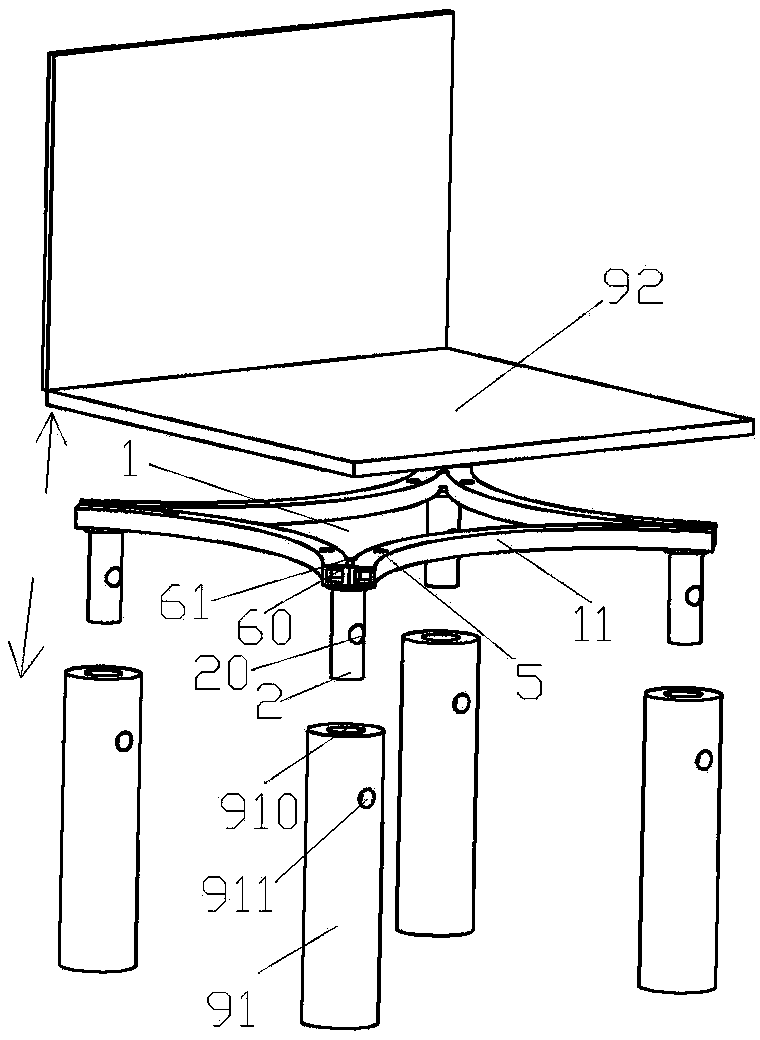
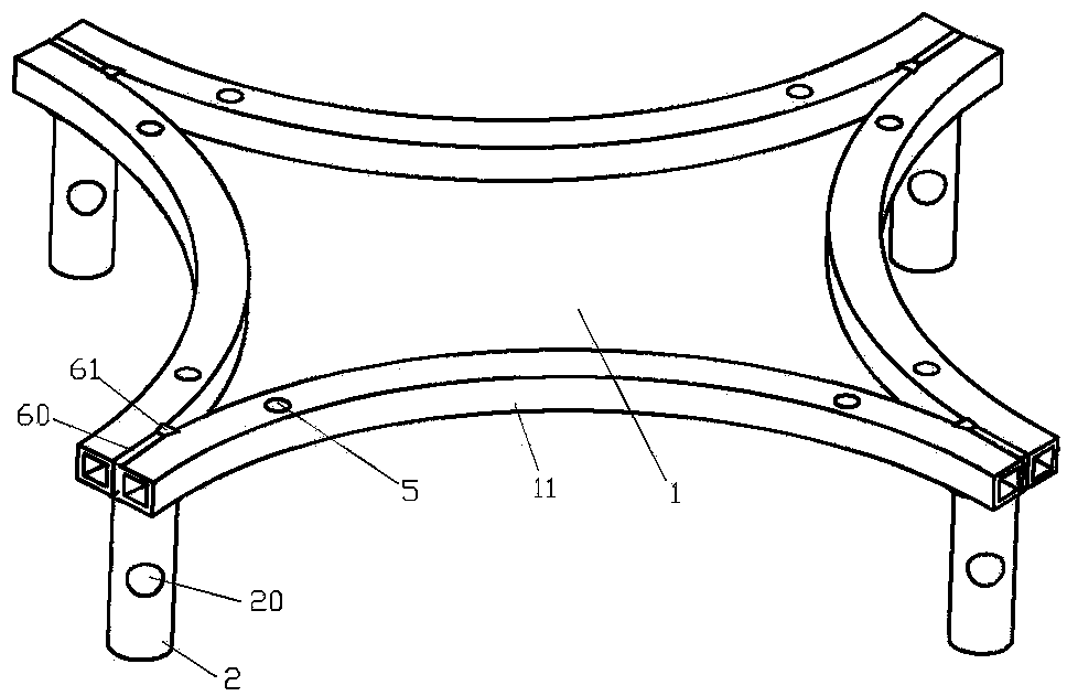
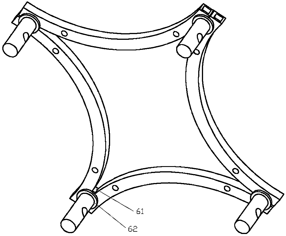
[0034] Example 1, such as figure 1 , 2 , shown in 3, a kind of detachable seat, is made up of seat body, cushion supporting frame and chair leg 91, and seat body comprises the cushion 92 that is used to accept human hip buttocks, and cushion supporting frame can be connected with seat cushion above The seat cushion support frame can be disassembled with the chair leg 91 at the bottom. The seat cushion support frame includes a load-bearing frame 1 with a flat upper surface formed by connecting four hollow metal tubes 11 and is fixed on the lower surface of the load-bearing frame 1. The support body 2 used to connect with the chair leg 91 can also be made of steel material, the hollow metal pipe 11 can preferably be a steel pipe, and the hollow metal pipe 11 is curved inward toward the center of the load-bearing frame 1, and the concave is hollow The metal tubes 11 are connected end to end in sequence, forming a structure in which adjacent hollow metal tubes 11 stick to eac...

Embodiment 2

[0036] Example 2, such as Figure 4 , 5 , 6, the difference from Embodiment 1 is that the hollow metal tube 11 deviates from the joint and extends toward the concave side of the load-bearing frame 1 to form an extension head pipe 110, and the extension head pipe 110 extended by the hollow metal pipe 11 A sealing end cover 3 is provided on the outer nozzle of the load-bearing frame 1 . Preferred way 1, the adjacent extension head tubes 110 are designed to be close to each other, and the gap value is between 0-0.5mm, which will have a good face shielding effect, especially when the human body makes some In non-standard sitting postures, for example, when a chair leg is tilted to cause the entire seat to tilt, the metal tube at the upper part of the load-bearing frame will actually press against the metal tube at the lower part, and at this time The extension head pipe 110 can effectively alleviate the deformation and other problems caused by the pressing effect; the second ...

Embodiment 3

[0037] Example 3, such as Figure 7 , 8 As shown, the difference between it and Embodiment 2 is that the lower end of the sealing end cap 3 located outside the tube and the lower end of the lateral positioning block 4 are connected together through a transitional connection structure. Since the lateral positioning block 4 has a better positioning and fixing effect on the metal pipe in the lateral direction due to the lateral barrier effect of the side wall of the embedded groove 40, in the vertical direction, if the metal pipe is subjected to an adverse force in the vertical direction, it will still easily occur. Problems such as positional movement in the up and down directions affect the structural alignment accuracy of the load-bearing frame 1, the convenience of welding, and the overall structural strength. The up and down positioning effect is good, the horizontal positioning effect is poor, and it is easy to move out from the nozzle, and the combination of the two ju...


PUM


Abstract

The invention relates to the technical field of furniture and particularly relates to a demountable chair. The demountable chair consists of a chair body, a seat supporting frame and chair legs, wherein the chair body comprises a seat which is used for undertaking the hip-thigh part of a human body, the upside of the seat supporting frame can be detached from the seat, the downside of the seat supporting frame can be detached from the chair legs, the seat supporting frame comprises a load bearing frame, which is provided with a flat upper surface and is formed through interconnecting four hollow metallic tubes, and supporting bodies which are fixed to the lower surface of the load bearing frame and are used for being connected with the chair legs, the four hollow metallic tubes are of an arc concave shape towards the center of the load bearing frame, the concave hollow metallic tubes are in end-to-end connection sequentially, and structures that adjacent hollow metallic tubes are abutted with one another by sidewalls are formed at junctions; the upper ends, in the vertical direction, of the supporting bodies are welded to the lower surfaces of the bottom walls, adjacent to abutted sidewalls, of adjacent hollow metallic tubes. The demountable chair has the advantages of simple and firm structure, strong carrying capacity, difficulty in deformation, convenience in production, convenience in demounting and low cost.

Description

technical field [0001] The invention relates to the technical field of furniture, in particular to a detachable seat. Background technique [0002] The most important function of the seat is to facilitate people to rest, and to enable users to sit in a comfortable sitting posture. A properly designed seat main support structure directly affects the quality, cost, portability, and service life of the seat. [0003] According to "A Preliminary Study on the Interpretation of Ancient Books", the chair originated in the Wei, Jin and Sui dynasties of our country. In the Song and Yuan dynasties, a commonly used seat appeared, called Hu bed, also known as Maza. Hu bed is easy to carry, but its There is no support in the middle of the cushion part, and the cushion will be obviously sunken after sitting down, and sitting for a long time will lead to deformation of the sitting posture, which will affect the user's health and experience. [0004] Similar to the support structure of th...

Claims


Application Information

Patent Timeline
IPC IPC(8): A47C4/02A47C7/00
Inventor 潘琦
Owner ZHEJIANG DEMURE FURNITURE CO LTD
Learn More