Internal and external supporting rod type cable-arch structure

A cable arch and rod type technology, which is applied in the field of inner and outer brace type cable arch structures, can solve the problems of chemical instability of the protective layer, PE chemical instability, structural safety hazards, etc., so as to improve the collapse resistance and prevent continuous collapse , The effect of eliminating potential safety hazards

Inactive Publication Date: 2014-08-20
HUAIHAI INST OF TECH
View PDF7 Cites 0 Cited by
  • Summary
  • Abstract
  • Description
  • Claims
  • Application Information

AI Technical Summary

Problems solved by technology

[0006] In general, there is one or more layers of PE protective layer on the surface of the cable 2, which is chemically unstable relative to the steel, so even if the friction force between the cable clamp 4 and the cable 2 is large enough during construction, it will not It can only keep the strut 3 vertical for a certain period of time, even if the friction test is done at that time, and the requirements are met, due to the chemical instability of PE, chemical changes (such as chemical decomposition, aging) will occur quickly, resulting in The cable slips at the connection point between the strut 3 and the cable 2, causing the cable 2 to become loose, thereby causing structural safety hazards

Method used


Image

  • Internal and external supporting rod type cable-arch structure
  • Internal and external supporting rod type cable-arch structure
  • Internal and external supporting rod type cable-arch structure

Examples


Embodiment Construction

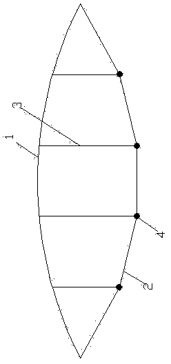
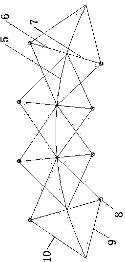
[0020] refer to image 3 , an inner and outer strut type cable-arch structure, comprising an upper string 5, the upper string 5 can also be an arch or a truss, on the upper string 5 along its length direction, several groups of string cables are arranged, and each group of string cables is connected to the upper string There are struts between the beams 5 , and the string cables and struts are in the same plane as the upper run beam 5 ; Each group of chord stay cables includes an upper stay cable 10 and a lower pull cable 9 arranged in a V shape on both sides of the upper string beam 5. The opening of the upper stay cable 10 is set downward, and the opening of the lower pull cable 9 is set upward. Both the front and rear free ends of the upper stay cable 10 and the lower stay cable 9 are respectively hinged with the upper run beam 5, and the hinge points on the same side coincide. Between the inflection point of the last stay cable 10 and the upper chord beam 5, there is an u...


PUM


Abstract

The invention discloses an internal and external supporting rod type cable-arch structure. The internal and external supporting rod type cable-arch structure comprises an upper chord beam. The upper chord beam is provided with a plurality of sets of chord inhaul cables. Each set of inhaul cables include an upper inhaul cable and a lower inhaul cable, wherein the upper inhaul cable and the lower inhaul cable are arranged on the upper side and the lower side of the upper chord beam and are respectively in a V type, an opening of the upper inhaul cable is downward, an opening of the lower inhaul cable is upward, the front free ends and the rear free ends of the upper inhaul cable and the lower inhaul cable are hinged to the upper chord beam, the hinge points on the same side coincide, an upper supporting rod is downwards arranged from the folding point of the upper inhaul cable and located between the folding point and the upper chord beam, a lower supporting rod is upwards arranged from the folding point of the lower inhaul cable and located between the folding point and the upper chord beam, and the upper supporting rod and the lower supporting are hinged to the same point on the upper chord beam. A front hinge point of a rear set of chord inhaul cables coincides with the hinge point of a front set of supporting rods. A rear hinge point of a front set of chord inhaul cables coincides with the hinge point of a rear set of supporting rods. After a certain upper inhaul cable or lower inhaul cable loses efficacy, the whole structure will not immediately lose efficacy, collapse resistance is improved, the height of the whole section increases, and the bearing capacity is largely improved.

Description

technical field [0001] The invention relates to a cable arch structure, in particular to an inner and outer brace type cable arch structure. Background technique [0002] At present, there are more and more applications of long-span steel structures in the field of civil engineering. However, with the increase of the span, the self-weight increases sharply, and the structure faces the contradiction of the mutual restriction of the use function, design rationality and economic indicators. In order to meet the function of the structure and reduce the structure's own weight to improve the rigidity of the structure, prestressed string beams equipped with cables are more and more used in long-span steel structures. Through the arrangement of prestressed cables and struts, the bearing capacity and stiffness of the long-span steel structure have been greatly improved. [0003] Existing cable-arch structures such as figure 1 As shown, the existing string girder includes the uppe...

Claims


Application Information

Patent Timeline
Patent Type & Authority Applications(China)
IPC IPC(8): E04B1/34E04B1/32E04B1/342
Inventor 宗钟凌吕凤伟
Owner HUAIHAI INST OF TECH
Why Eureka
Try Eureka