
Self-circulating suction air injection device and method based on multi-stage axial flow compressor hub end wall

An axial flow compressor and jet device technology, which is applied in the directions of jet propulsion devices, gas turbine devices, and components of pumping devices for elastic fluids, etc., can solve the problems of channel blockage, increase total pressure loss, etc. Loss, improved efficiency, small loss effect

Active Publication Date: 2016-04-20
青岛中科国晟动力科技有限公司
View PDF6 Cites 0 Cited by
  • Summary
  • Abstract
  • Description
  • Claims
  • Application Information

AI Technical Summary

Problems solved by technology

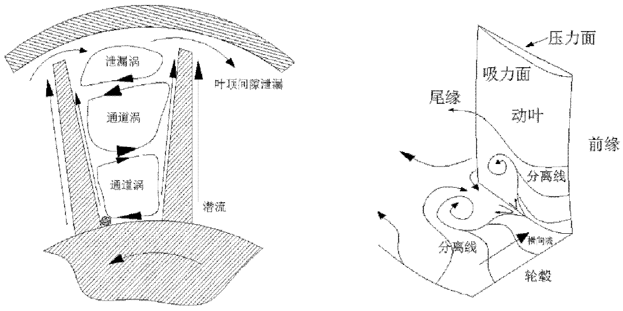
The hub-corner separation vortex will roll up and mix with the shedding vortex on the suction surface, causing channel blockage and increasing the total pressure loss

Method used


Image

  • Self-circulating suction air injection device and method based on multi-stage axial flow compressor hub end wall
  • Self-circulating suction air injection device and method based on multi-stage axial flow compressor hub end wall
  • Self-circulating suction air injection device and method based on multi-stage axial flow compressor hub end wall

Examples


Embodiment Construction

[0036] In order to make the object, technical solution and advantages of the present invention clearer, the present invention will be described in further detail below in conjunction with specific embodiments and with reference to the accompanying drawings.

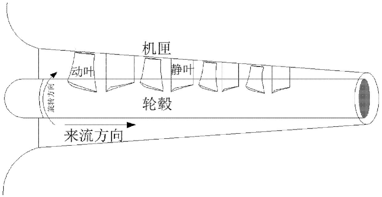
[0037] Such as figure 1 as shown, figure 1 It is a structural schematic diagram of a multi-stage axial flow compressor in the prior art. The multi-stage axial flow compressor includes: moving blades, stationary blades, casing and hub, wherein the moving blades are installed on the hub, and the stationary blades are installed on the casing. . During the rotation of the multi-stage axial flow compressor, the rotor blades rotate together with the hub, and then do work on the incoming flow to increase the pressure and speed of the intake air. When the gas passes through the stator blades, the static pressure increases According to the law of conservation of energy, the pressure increases and the velocity decreases. In th...


PUM


Abstract

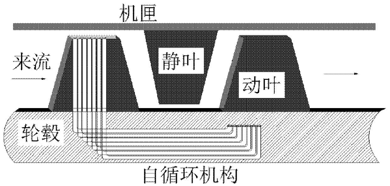
The invention discloses a hub end wall self-circulation suction jet device and method based on a multistage axial gas compressor. A self-circulation mechanism is arranged between a rear stage blade channel interior hub and a front stage movable blade top of the multistage axial gas compressor, the static pressure difference between the wall of the rear stage blade channel interior hub and the front stage movable blade top of the multistage axial gas compressor is utilized, and gas in the area of the rear stage blade channel interior hub is guided to the front stage movable blade top through the self-circulation mechanism for radial jetting accordingly. High-pressure eddy currents in the area of the rear stage blade channel interior hub of the multistage axial gas compressor can be fully utilized, radial jetting is carried out at the movable blade top, intensity of leakage currents in the area of the blade top is reduced, dual purposes of improving stall margin and efficiency are achieved, and the axial gas compressor can be operated under operating conditions with high-pressure ratios and wide stall margins.

Description

technical field [0001] The invention relates to the technical field of gas turbines, in particular to a self-circulating suction air injection device and method based on the hub end wall of a multistage axial flow compressor. Background technique [0002] As one of the key components of gas turbine / aeroengine, the axial flow compressor has always been a hot and difficult point in the field of turbomachinery to improve its working stability. At present, various explorations have been made on the stability expansion measures to improve the stability margin in the world, mainly including adjustable blades, casing treatment (circumferential grooves and axial slits), blade tip air injection, large and small blades, and intermediate stage air release, etc. . [0003] As an effective control method, tip injection has attracted widespread attention in the world, and a lot of research has been done on its stability expansion mechanism and its relationship with compressor flow instab...

Claims


Application Information

Patent Timeline
Patent Type & Authority Patents(China)
IPC IPC(8): F04D29/32F04D29/00F02C9/20
Inventor 李继超林峰王偲臣杜娟聂超群刘海清
Owner 青岛中科国晟动力科技有限公司
Learn More