Cantilever structure of operation stable

A technology of operating table and cantilever, which is applied in the direction of machine table/support, supporting machine, mechanical equipment, etc., and can solve the problems of cable entanglement, cable damage, operating table disconnection, etc.

Active Publication Date: 2014-08-20
JIANGSU YONGJIN METAL TECHNOLOGY CO LTD
View PDF4 Cites 4 Cited by
  • Summary
  • Abstract
  • Description
  • Claims
  • Application Information

AI Technical Summary

Problems solved by technology

[0002] On the production line of large-scale equipment, passwords are input to the large-scale equipment through an operation console that is externally connected to the equipment or installed near the equipment. The console has a display screen and an operation box. The cable passes through the interior,

Method used


Image

  • Cantilever structure of operation stable
  • Cantilever structure of operation stable

Examples


Embodiment Construction

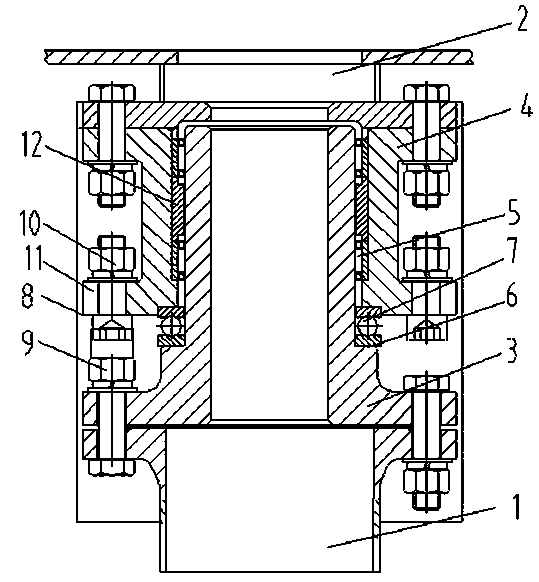
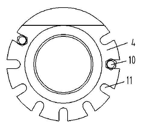
[0015] The cantilever structure of the operating table of the present invention includes a rotating arm 1 through which cables are threaded and a bracket 2 located above the rotating arm 1 . In order to limit the full circle rotation of the pivoting arm 1 relative to the bracket 2, a limited full circle rotation structure is arranged between the pivot arm 1 and the bracket 2. The sleeve on the shaft 3, the bearing 5 between the sleeve and the mandrel 3, the fastening bolt 9 at the lower end of the mandrel is bolted to the rotating arm 1, there is a gap between the upper end of the mandrel and the bracket 2, the sleeve The upper end of the sleeve is bolted to the bracket 2, and the lower end of the sleeve and the lower end of the mandrel is provided with a slewing bearing 7 that is against the lower end of the sleeve and the preset shoulder 6 on the mandrel 3, and the lower end of the sleeve is provided with a An integral flange 8 is provided with a limit block 10 against the f...


PUM


Abstract

The invention discloses a cantilever structure of an operation stable. The cantilever structure comprises a rotating arm and a bracket, wherein a cable penetrates through the rotating arm, and the bracket is located above the rotating arm. The cantilever structure is characterized in that a complete cycle rotation limiting structure is arranged between the rotating arm and the bracket and comprises a central spindle, a sleeve and a bearing, wherein the central axis of the central spindle is vertically arranged, the central spindle is sleeved with the sleeve in a spaced mode, and the bearing is located between the sleeve and the central spindle. The lower end of the central spindle is connected to the rotating arm in a bolted mode, the central spindle penetrates through the sleeve, and the upper end of the sleeve is fixed to the operation stable. The bearing is arranged between the central spindle and the sleeve. It is guaranteed that the upper end of the central spindle does not abut against the operation stable, and a rotation bearing abuts against a preset shoulder on the central spindle to axially fix the lower end of the sleeve. In order to achieve complete cycle rotation limiting, limiting blocks are arranged at the lower end of the sleeve and just abut against fastening bolts for connecting the central spindle and the rotating arm when the sleeve rotates to a certain position, and therefore complete cycle rotation, relative to the rotating arm, of the operation table is achieved.

Description

technical field [0001] The invention relates to a cantilever structure of an operating table, in particular to a cantilever structure of an operating table that limits full circle rotation. Background technique [0002] On the production line of large-scale equipment, passwords are input to the large-scale equipment through an operation console that is externally connected to the equipment or installed near the equipment. The console has a display screen and an operation box. The cable passes through the interior, and the console can rotate relative to the boom. However, in actual use, if the console rotates around the boom relative to the entire circle, there will be phenomena such as entanglement of the cables in the boom, which is likely to cause the cable to Broken or disconnected from the console. Contents of the invention [0003] The technical problem to be solved by the present invention is to provide a cantilever structure of the console, which can limit ...

Claims


Application Information

Patent Timeline
IPC IPC(8): F16M11/06F16M11/16
Inventor 王勇
Owner JIANGSU YONGJIN METAL TECHNOLOGY CO LTD
Why Eureka
Try Eureka