Device for measuring micro-impulse by adopting linear frequency modulation double-beam laser heterodyne method and torsion method and measuring method of device

A technology of linear frequency modulation and laser heterodyning, which is applied to measuring devices, force/torque/power measuring instruments, instruments, etc., and can solve problems such as low measurement accuracy

Inactive Publication Date: 2014-08-20
HEILONGJIANG UNIV
View PDF7 Cites 6 Cited by
  • Summary
  • Abstract
  • Description
  • Claims
  • Application Information

AI Technical Summary

Problems solved by technology

[0005] The present invention aims to solve the problem of low measurement accuracy of existing devices and methods for measuring micro-impulse. The present invention provides a device for measuring micro-impulse using chirped double-beam laser heterodyne method and torsion pendulum method and a measurement method for the device.

Method used


Image

  • Device for measuring micro-impulse by adopting linear frequency modulation double-beam laser heterodyne method and torsion method and measuring method of device
  • Device for measuring micro-impulse by adopting linear frequency modulation double-beam laser heterodyne method and torsion method and measuring method of device
  • Device for measuring micro-impulse by adopting linear frequency modulation double-beam laser heterodyne method and torsion method and measuring method of device

Examples


specific Embodiment approach 1

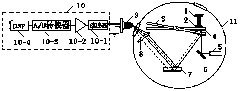
[0054] Specific implementation mode one: see figure 1 Describe this embodiment, the device for measuring micro-impulse using chirped double-beam laser heterodyne method and torsion method described in this embodiment, it includes pulse laser 1, working medium target 2, standard beam 3, and No. 2 plane mirror 4 , chirp laser 5, No. 1 plane mirror 6, plane standard mirror 7, converging lens 8, photodetector 9, signal processing system 10 and vacuum chamber 11;

[0055] The pulse laser 1, working medium target 2, standard beam 3, No. 2 plane mirror 4, chirp laser 5, No. 1 plane mirror 6, plane standard mirror 7 and converging lens 8 are all placed in a vacuum chamber,

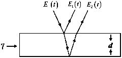
[0056] A working fluid target 2 is fixed on the plane at one end of the beam of the standard beam 3, and a No. 2 plane reflector 4 is pasted on the opposite position of the other side plane of the standard beam 3 opposite to the working fluid target 2; 3 In the horizontal state, the optical axis of the laser ligh...

specific Embodiment approach 2

[0060] Embodiment 2: The difference between this embodiment and the device for measuring micro-impulse using chirped double-beam laser heterodyne method and torsion method described in Embodiment 1 is that the signal processing system 10 includes a filter 10-1 , preamplifier 10-2, A / D converter 10-3 and DSP10-4, the signal output end of described filter 10-1 is connected with the amplified signal input end of preamplifier 10-2, preamplifier The amplified signal output end of 10-2 is connected with the analog signal input end of A / D converter 10-3, and the digital signal output end of A / D converter 10-3 is connected with the data signal input end of DSP10-4.

specific Embodiment approach 3

[0061] Specific embodiment three: This embodiment is based on the device for measuring micro-impulse by using chirped double-beam laser heterodyne method and torsion method described in specific embodiment one or two to realize the measurement method of micro-impulse. The specific process of this method is as follows:

[0062] Firstly, the pulsed laser 1, the chirp laser 5, the photodetector 9 and the signal processing system 10 are put into operation, and the swing angle θ′ of the standard beam 3 is obtained by measuring,

[0063] Second, according to

[0064] I ′ = 2 Jω D · θ ′ = 4 πJ DT ′ · θ ′ (Formula 1),

[0065] Calculate and obtain the micro-pulse I' generated by the...


PUM

PropertyMeasurementUnit
thicknessaaaaaaaaaa
refractive indexaaaaaaaaaa

Abstract

The invention provides a device for measuring a micro-impulse by adopting a linear frequency modulation double-beam laser heterodyne method and a torsion method, and a measuring method of the device and belongs to the field of micro-impulse measurement. The problem that an existing device and method for measuring the micro-impulse are low in measurement precision is solved. The linear frequency modulation double-beam laser heterodyne method is applied to the micro-impulse measuring method, measurement of the micro-impulse is converted into measurement of the torsion angle of a standard beam, information of the torsion angle of the standard beam to be measured can be obtained indirectly by measuring the incident light refraction angle of a plane standard mirror, and the measurement precision is effectively improved; when the rotating angle is smaller than five degrees, the linear relation between the measured micro-impulse and the incidence angle theta 0 is formed, a measurement error is smaller than 0.52%, the requirement for impulse measurement from a laser micro-thruster can be met, and a good measuring means can be provided for evaluating the performance of the laser micro-thruster. The device is mainly applied to evaluation of the laser micro-thruster.

Description

technical field [0001] The invention belongs to the field of micro-pulse measurement. Background technique [0002] Laser micro-thrusters have broad and in-depth application prospects in the field of attitude and orbit control of micro-satellites. Significant advantages such as digital control have attracted extensive attention from scholars at home and abroad. The impulse is an important parameter reflecting the performance of the laser micro thruster, which is characterized by a small magnitude, about 10 -7 ~10 -5 N·s. In 1999, Phipps et al. from the Photonic Associates group proposed to use the torsion pendulum system to measure the micro-impulse generated by the laser micro-thruster, and used it to test the performance parameters of the micro-thruster; in 2002, Phipps et al. improved the torsion system, and then The domestic University of Science and Technology of China and the Institute of Equipment Command Technology have also carried out related research. Judging...

Claims


Application Information

Patent Timeline
Patent Type & Authority Applications(China)
IPC IPC(8): G01L5/00
Inventor 李彦超杨九如高扬冉玲苓柳春郁杨瑞海杜军丁群王春晖马立峰于伟波
Owner HEILONGJIANG UNIV
Why Eureka
Try Eureka