Turn-on voltage testing method of switching tube

A technology of turn-on voltage and test method, which is applied in the field of turn-on voltage test of switching tubes, and can solve problems such as affecting test efficiency and long test time

Active Publication Date: 2014-08-20
CSMC TECH FAB2 CO LTD
View PDF7 Cites 6 Cited by
  • Summary
  • Abstract
  • Description
  • Claims
  • Application Information

AI Technical Summary

Problems solved by technology

However, when testing products with high turn-on voltage, there may be a large gap between the lower initial test voltage a

Method used


Image

  • Turn-on voltage testing method of switching tube

Examples


Embodiment Construction

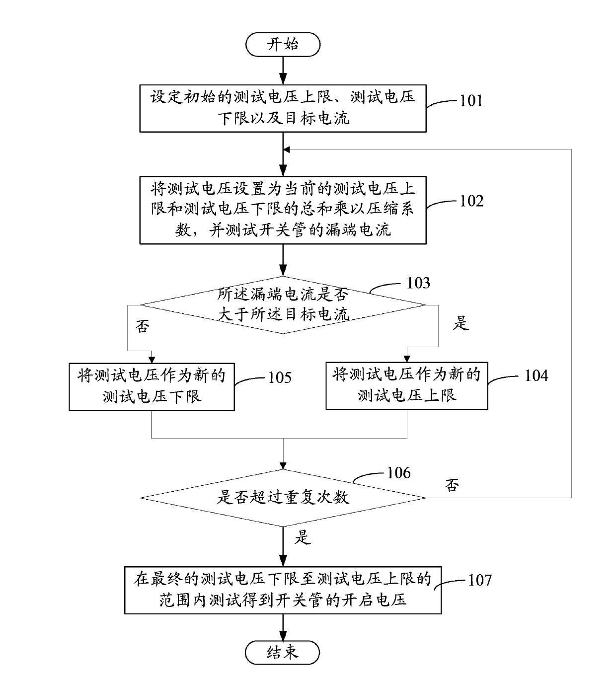
[0015] Such as figure 1 As shown, it is a flow chart of a method for testing the turn-on voltage of a switch tube according to an embodiment. The method includes the following steps.

[0016] S101: Setting an initial test voltage upper limit, a test voltage lower limit and a target current. Since the voltage applied to the gate of the switch tube is lower than the breakdown voltage of the gate oxide when testing the turn-on voltage of the switch tube, otherwise the switch tube will be broken down and damaged. Therefore, the upper limit of the test voltage Vgmax is generally lower than the breakdown voltage of the gate oxide, generally around 5 volts. In this embodiment, the initial upper limit of the test voltage is set to 5 volts. In order to ensure that the turn-on voltage can be detected, the lower limit Vgmin of the test voltage is set to 0 volts at the same time. The target current is the drain current of the switch tube when the gate voltage reaches the turn-on voltag...


PUM


Abstract

The invention discloses a turn-on voltage testing method of a switching tube. The testing method comprises the following steps that: an initial testing voltage upper limit, an initial testing voltage lower limit, and a target current are set; the testing voltage is set as a value that is obtained by multiplying a sum of the initial testing voltage upper limit and the initial testing voltage lower limit by a compressibility coefficient, and a drain terminal current of the switching tube is tested; a relation between the drain terminal current and the target current is determined; if the drain terminal current is larger than the target current, the testing voltage is used as a new testing voltage upper limit, and if the drain terminal current is less than the target current, the testing voltage is used a new testing voltage lower limit; the above steps are repeated by using the new testing voltage upper limit or the new testing voltage lower limit and preset repletion times so as to obtain a first testing voltage upper limit and a first testing voltage lower limit; and a turn-on voltage of the switching tube is tested and obtained in a range from the first testing voltage lower limit to the first testing voltage upper limit. Compared with the traditional testing method, the provided method has the high testing efficiency.

Description

technical field [0001] The invention relates to component testing technology, in particular to a method for testing the turn-on voltage of a switch tube. Background technique [0002] To determine the turn-on voltage of the finished switching tube, testing is required. Taking the mode tube as an example, a certain voltage is added to its gate as a test voltage, and a fixed power supply is applied between its source and drain, so that a current flows between the source and drain, and it is tested whether the current reaches the target current. When the target current is reached, the corresponding test voltage is the turn-on voltage. [0003] The traditional method of testing the turn-on voltage is to start from 0 volts, gradually increase the test voltage with a fixed step size, and then check whether the current reaches the target current. In order to achieve higher accuracy, the fixed step size is usually small, such as 0.05 volts. However, when testing products with hig...

Claims


Application Information

Patent Timeline
IPC IPC(8): G01R31/26
Inventor 连晓谦王明凌耀君
Owner CSMC TECH FAB2 CO LTD
Why Eureka
Try Eureka