
Method for tracking radio frequency tag track

A trajectory tracking and radio frequency tag technology, applied in electromagnetic radiation induction, special data processing applications, measurement devices, etc., can solve the problems of white noise and diversity affecting the positioning accuracy of RFID tags

Active Publication Date: 2014-08-20
NANJING TAIXI INFORMATION TECH
View PDF6 Cites 19 Cited by
  • Summary
  • Abstract
  • Description
  • Claims
  • Application Information

AI Technical Summary

Problems solved by technology

Obviously, errors introduced by white noise and diversity will affect the positioning accuracy of RFID tags

Method used


Image

  • Method for tracking radio frequency tag track
  • Method for tracking radio frequency tag track
  • Method for tracking radio frequency tag track

Examples


Embodiment Construction

[0064] The present invention will be further described below with reference to the drawings and embodiments. It can be understood that the specific embodiments described here are only used to explain the present invention, but not to limit the present invention. In addition, it should be noted that, for ease of description, the drawings only show a part but not all of the content related to the present invention.

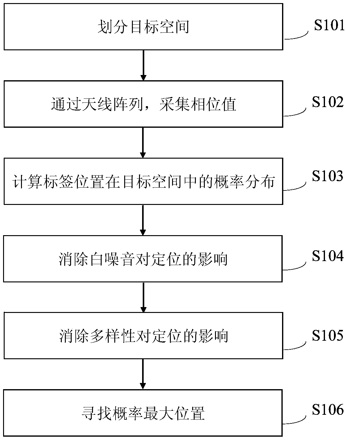
[0065] Please refer to figure 1 As shown, figure 1 This is a flow chart of a method for tracking a radio frequency tag track provided by an embodiment of the present invention.

[0066] Real-time tracking issues are defined as:

[0067] The trajectory equation of the label can be expressed as:

[0068] f(t)=f(t 0 )+(t-t 0 )·V(t)

[0069] Where f(t) represents the position of the tag at time t, v(t) is the velocity vector of the tag at time t, t 0 Is the initial moment.

[0070] The goal of this method is to find the position f(t) of the moving label at any time t. The tag...


PUM


Abstract

The invention provides a method for tracking a radio frequency tag track. A moving RFID tag is located and tracked in real time at the millimeter level through phase values. The method specifically includes the following steps that A, target space is divided; B, the phase values are collected through an antenna array; C, probability distribution of the position of the tag in the target space is calculated; D, influence on localization from white noise is eliminated; E, influence on localization from diversity is eliminated; F, the maximum probability position is searched for. According to the method, influence from white noise and diversity in RFID localization can be effectively eliminated and under the condition that only a small number of antennas are available, the moving RFID tag is located and tracked with high accuracy in real time through the virtual antenna array established according to the virtual antenna technology and under the condition of a small number of antennas.

Description

Technical field [0001] The invention relates to the technical field of indoor positioning, in particular to a method for tracking a radio frequency tag track. Background technique [0002] Whether in the Internet of Things or RFID applications, positioning technology has always been a technical hot spot that has been widely studied due to urgent and diverse application requirements. Satellite positioning system (GPS) is often used to locate people and equipment, such as car navigation, military operations, etc. However, in the actual environment, the coverage of the satellite positioning system still has obvious limitations due to its technical characteristics. Although the satellite positioning system can perform effective positioning outdoors, the satellite positioning system will fail in most indoor or obstructed environments due to the need for line-of-sight transmission and reception of satellite signals. At the same time, in large indoor environments such as warehouses, a...

Claims


Application Information

Patent Timeline
IPC IPC(8): G01S5/06G06K7/10G06F19/00
CPCG01S5/06
Inventor 陈烨魁杨磊刘云浩
Owner NANJING TAIXI INFORMATION TECH
Learn More