Centrifugal compressor
A centrifugal compressor and impeller technology, applied in mechanical equipment, non-variable-capacity pumps, non-displacement pumps, etc., can solve the problems of production cost, waste of operation time, etc., and achieve the reduction, suppression and elimination of static pressure recovery. Uneven velocity distribution, effect of reducing stagnation area
- Summary
- Abstract
- Description
- Claims
- Application Information
AI Technical Summary
Problems solved by technology
Method used
Image
Examples
Embodiment 1
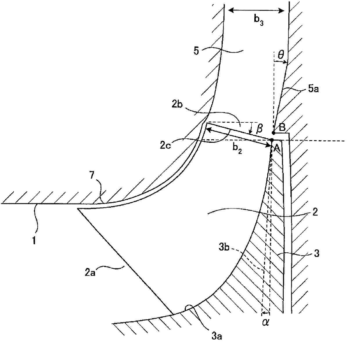
[0040] Combine figure 1 The device according to Embodiment 1 of the present invention will be described. This device is the same as a conventional centrifugal compressor, and mainly includes a suction port 1, an impeller 2, a hub 3, a rotating shaft 4, a diffuser 5, and a scroll 6. The impeller 2 is connected to the rotating shaft 4 via the hub 3. In addition, the diffuser 5 is arranged downstream of the impeller 2, the flow path faces away from the rotating shaft 4, and the outlet faces the radial direction of the meridian surface. Furthermore, the scroll 6 is arranged at The downstream of the diffuser 5 is connected to the outlet of the diffuser 5. It should be noted that the rotating shaft 4 and the scroll 6 are figure 1 Not shown in, but the same as the prior art.
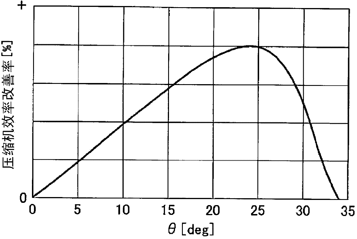
[0041] Furthermore, similar to the prior art, the suction port 1 has a function of guiding gas to the impeller 2. The gas guided to the impeller 2 rotates the impeller 2 by the rotating shaft 4, so that the ga...
Embodiment 2
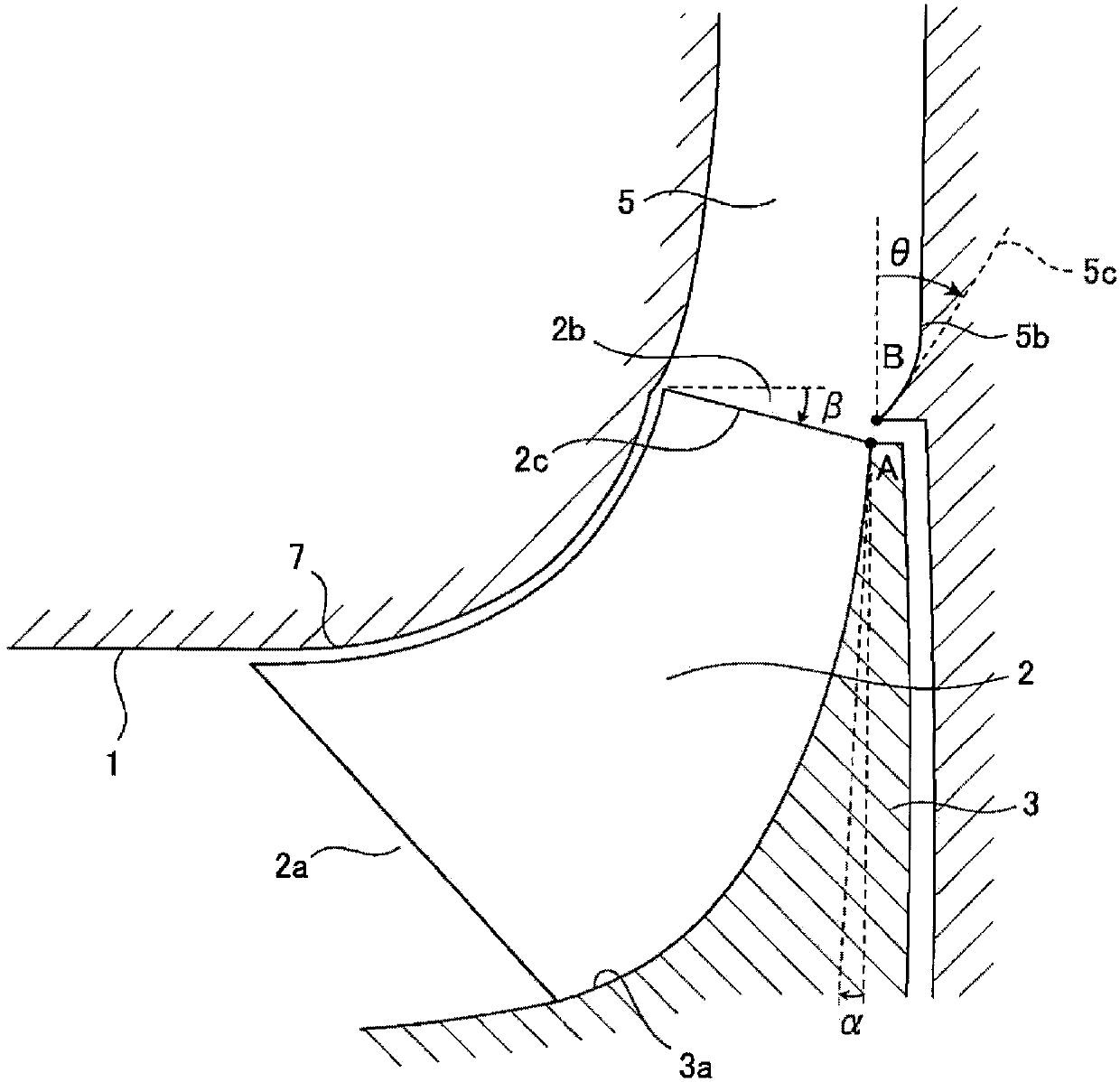
[0051] The device related to Embodiment 2 of the present invention is an improved device of the device related to Embodiment 1. Figure 4 The difference between the device in Example 1 and this device is shown. In the device according to Embodiment 1, the diffuser inlet hub side line 5a is a straight line. Therefore, when the outlet of the diffuser 5 is directed in the radial direction, the angle of the diffuser 5 must be changed at a certain point. Thus, as Figure 4 As shown, a stagnation area 11 where the flow of gas is stagnant is formed. Shear stress acts between the gas accumulated in the stagnation area 11 and the flowing gas, which may cause energy loss. This device is a device that reduces the retention area 11.
[0052] This device is the same as the device involved in embodiment 1 and the prior art, such as image 3 The shown mainly includes a suction port 1, an impeller 2, a hub 3, a rotating shaft 4, a diffuser 5, and a scroll 6. The impeller 2 is connected to the ...
PUM
 Abstract
Description
Claims
Application Information
 - R&D
- Intellectual Property
- Life Sciences
- Materials
- Tech Scout
- Unparalleled Data Quality
- Higher Quality Content
- 60% Fewer Hallucinations
Browse by: Latest US Patents, China's latest patents, Technical Efficacy Thesaurus, Application Domain, Technology Topic, Popular Technical Reports.
© 2025 PatSnap. All rights reserved.Legal|Privacy policy|Modern Slavery Act Transparency Statement|Sitemap|About US| Contact US: help@patsnap.com


