
Detachable self-locking type zipper puller

A zipper puller and self-locking technology, which is applied in the field of zipper pullers, can solve the problems of small caps, difficulties, jamming, etc., and achieve the effect of firm assembly, high production continuity, and not easy to twist

Active Publication Date: 2014-08-27
FUJIAN SBS ZIPPER SCI & TECH CO LTD
View PDF9 Cites 4 Cited by
  • Summary
  • Abstract
  • Description
  • Claims
  • Application Information

AI Technical Summary

Problems solved by technology

However, since the left and right end edges of the first and second column portions have raised support walls 24a, 25a, at least the front and rear end portions of the handle holder 40 are fitted and supported between the left and right support walls 24a, 25a. , due to the long joint area of ​​the mating part, it is more difficult for the handle holder of the zipper head, that is, the cap to be assembled automatically. If the feeding is not fully in place, it is easy to jam and cause production to stop; at the same time, the cap is small in size and is different from the left and right The support wall is assembled without gaps, and it is inconvenient to use hands or tools to pry off the cap. It is very difficult to disassemble the cap and replace the pull piece or horse hook, etc.; moreover, the joint part 48 is arranged on the front and rear side walls of the cap. On the front and rear inner surfaces of 42, if you want to remove the cap, you need to break the cap outward along the length direction of the cap. cover, and the structure of the first and second column parts of the slider body is also relatively complicated, and the left and right support walls are thin-walled structures, which are easy to break and affect the life and appearance of the zipper head

Method used


Image

  • Detachable self-locking type zipper puller
  • Detachable self-locking type zipper puller
  • Detachable self-locking type zipper puller

Examples


Embodiment Construction

[0024] Preferred embodiments of the present invention will be described in detail below in conjunction with the accompanying drawings.

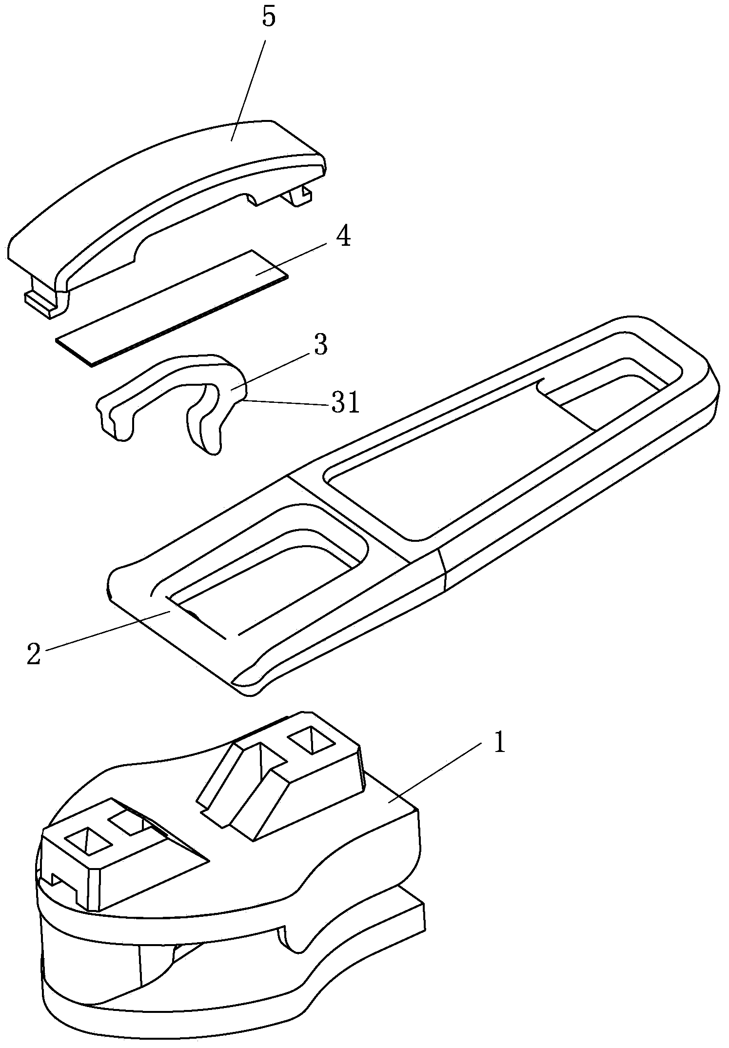
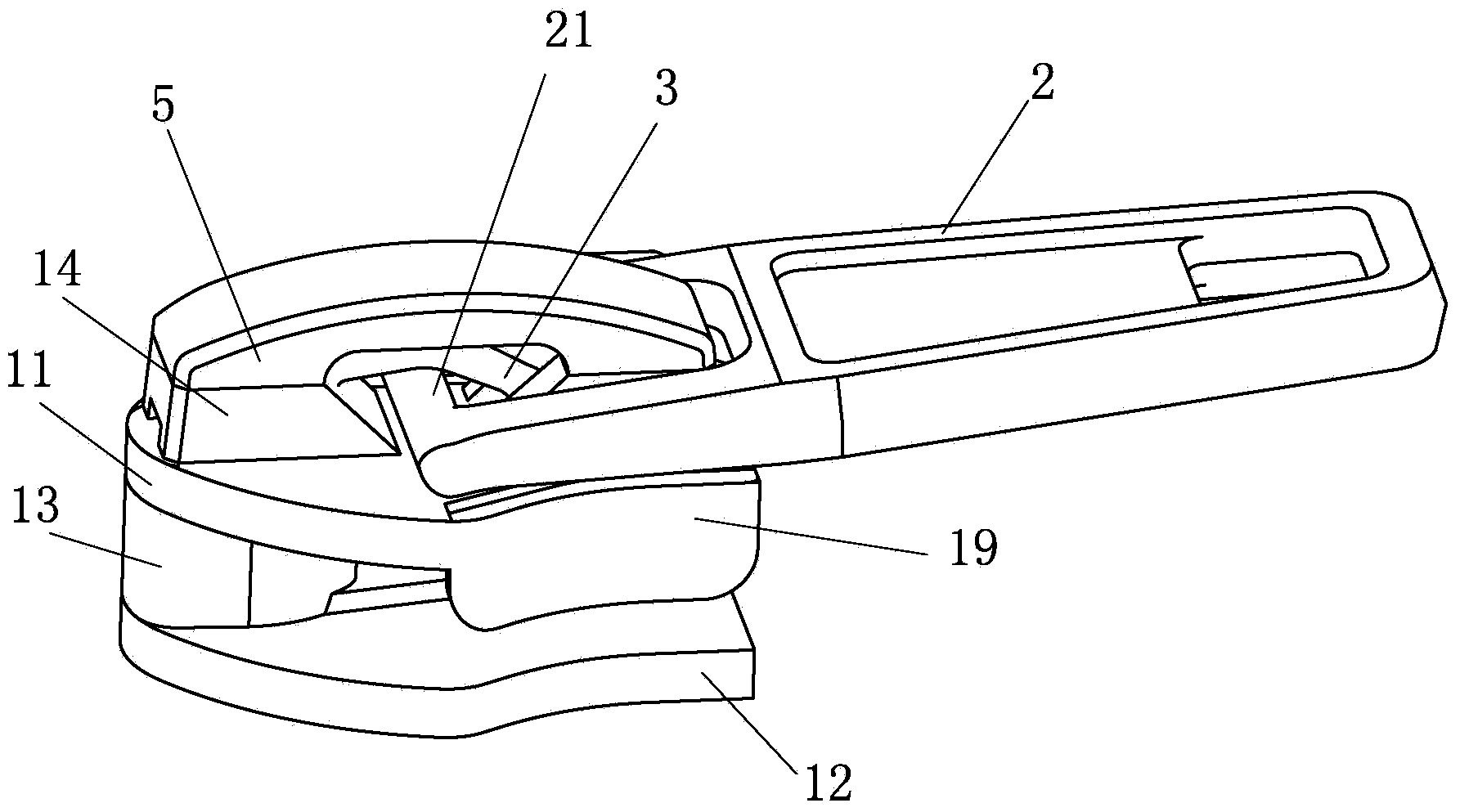
[0025] Such as Figure 1 to Figure 4 As shown, a detachable self-locking zipper head includes a slider body 1, a self-locking device, a pull tab 2 and a cap 5, and the slider body 1, the pull tab 2 and the cap 5 can utilize thermoplastic resin (such as Polyamide, polypropylene) or thermoplastic resin with wear-resistant reinforcing agent is made by injection molding. Of course, these three parts can also be made of metal material through die casting. Wherein, the slider body 1 has an upper plate 11 and a lower plate 12 supported and connected by a guide post 13. The upper plate 11 and the lower plate 12 have a large end and a small end, and the width of the large end is greater than that of the small end. In the following description , the big end of the slider body 1 is defined as the front end, and the small end is defined as the rear end...


PUM


Abstract

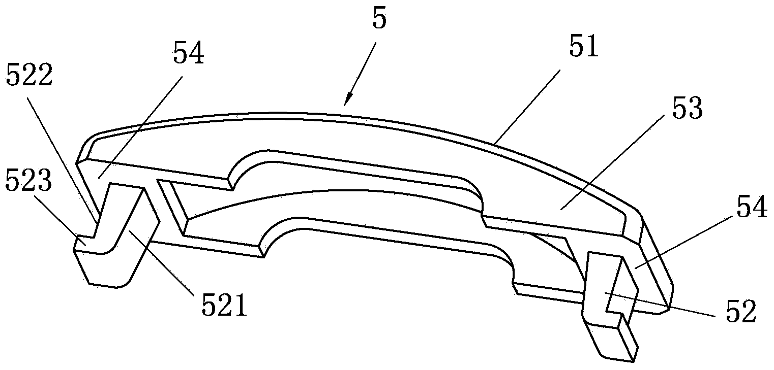
The invention provides a detachable self-locking type zipper puller. The detachable self-locking type zipper puller comprises a sliding block body, a self-locking device, a pull piece and a cap cover. The sliding block body is provided with an upper plate and a lower plate, wherein the upper plate and the lower plate are supported by and connected through a guide post. The front and the rear of the top face of the upper plate stretch upwards to form a first post body and a second post body. The first post body and the second post body are provided with first insertion holes extending downwards from the top faces of the post bodies. The bottoms of the first insertion holes extend towards the front end and the rear end of the sliding block body to form second insertion holes. The front and the rear of the top wall of the cap cover stretch downwards to form insertion pieces. The lower ends of the insertion pieces are bent and stretch towards the front end and the rear end of the cap cover. The insertion pieces can slide into the first insertion holes under the action of assembly force in an elastic deformation mode, and the bent portions of the insertion pieces can stretch into the second insertion holes to make the cap cover connected with the sliding block body in a limited mode. According to the self-locking type zipper puller, the cap cover and the sliding block body can be firmly connected without adopting a riveted mode in the combining process, the cap cover can be conveniently and harmlessly detached, and the zipper puller is simple in structure.

Description

technical field [0001] The invention relates to the technical field of zipper sliders, in particular to a detachable self-locking zipper slider. Background technique [0002] The zipper is a commonly used connection accessory. The zipper head includes components such as a slider body, a pull piece and a cap. The slider body is mainly composed of an upper plate, a lower plate and a guide post. Existing zipper sliders can be roughly divided into self-locking zipper sliders and non-self-locking zipper sliders. Non-self-locking zipper sliders may slide along the zipper tape under non-human conditions, while self-locking zipper sliders can prevent sliding under non-human operating conditions through a specially designed self-locking mechanism. The combination of the cap of the existing metal zipper puller and the slider body is realized by dot riveting, and the cap is deformed by external force to realize the combination with the slider body, while the plastic zipper cannot use ...

Claims


Application Information

Patent Timeline
IPC IPC(8): A44B19/30
Inventor 高秀忠杨涛张田朱松峰
Owner FUJIAN SBS ZIPPER SCI & TECH CO LTD
Learn More