
Roll stand for absorbing rolling forces

A technology of roll mill and rolling force, which is applied in the field of roll racks, can solve the problems of large modification costs, etc., and achieve the effect of simple roll adjustment and simplified roll adjustment

Inactive Publication Date: 2014-08-27
SMS MEER
View PDF0 Cites 0 Cited by
  • Summary
  • Abstract
  • Description
  • Claims
  • Application Information

AI Technical Summary

Problems solved by technology

It will be understood that the conversion of such a rolling mill to a different rolling pass or wear-related conversion would involve correspondingly large conversion costs, since the quick-release components fastened to the individual roll stands must be replaced accordingly. Roll elements on the roll shaft to set the rolling mill to a new rolling pass

Method used


Image

  • Roll stand for absorbing rolling forces
  • Roll stand for absorbing rolling forces
  • Roll stand for absorbing rolling forces

Examples


Embodiment Construction

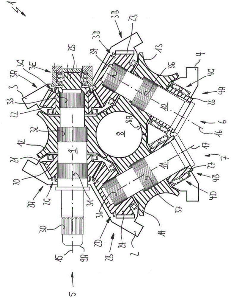
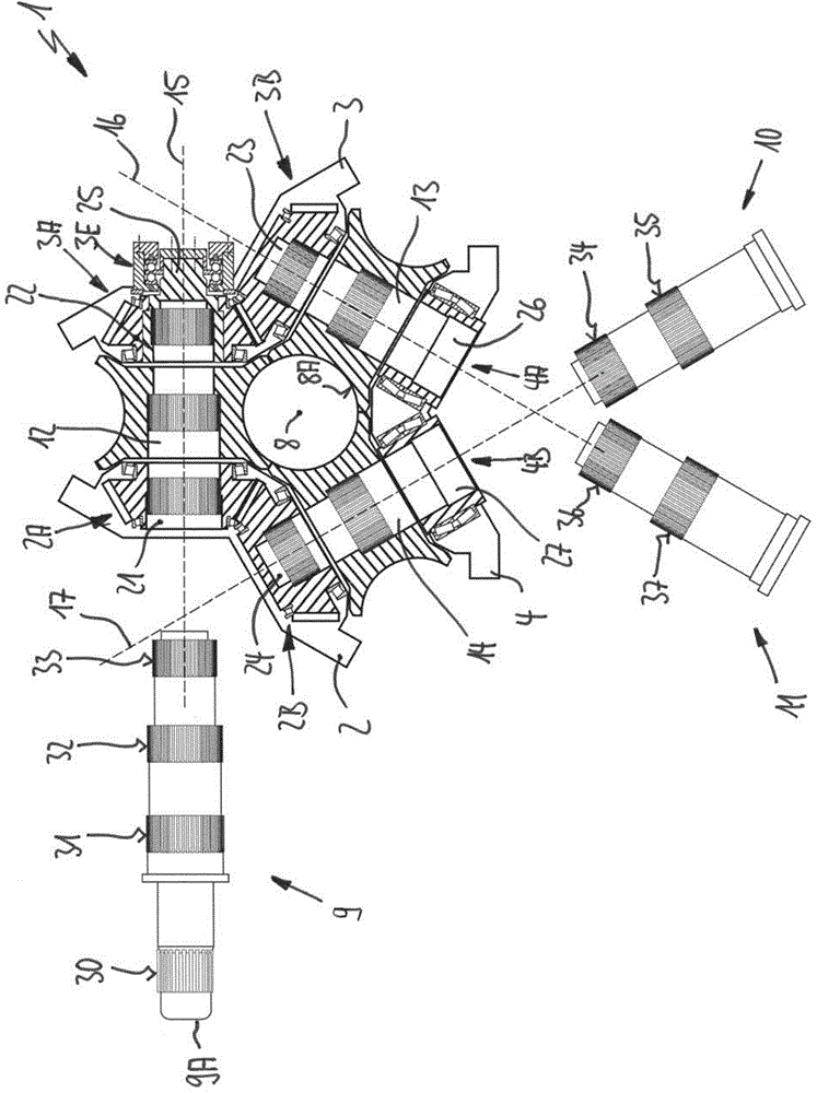
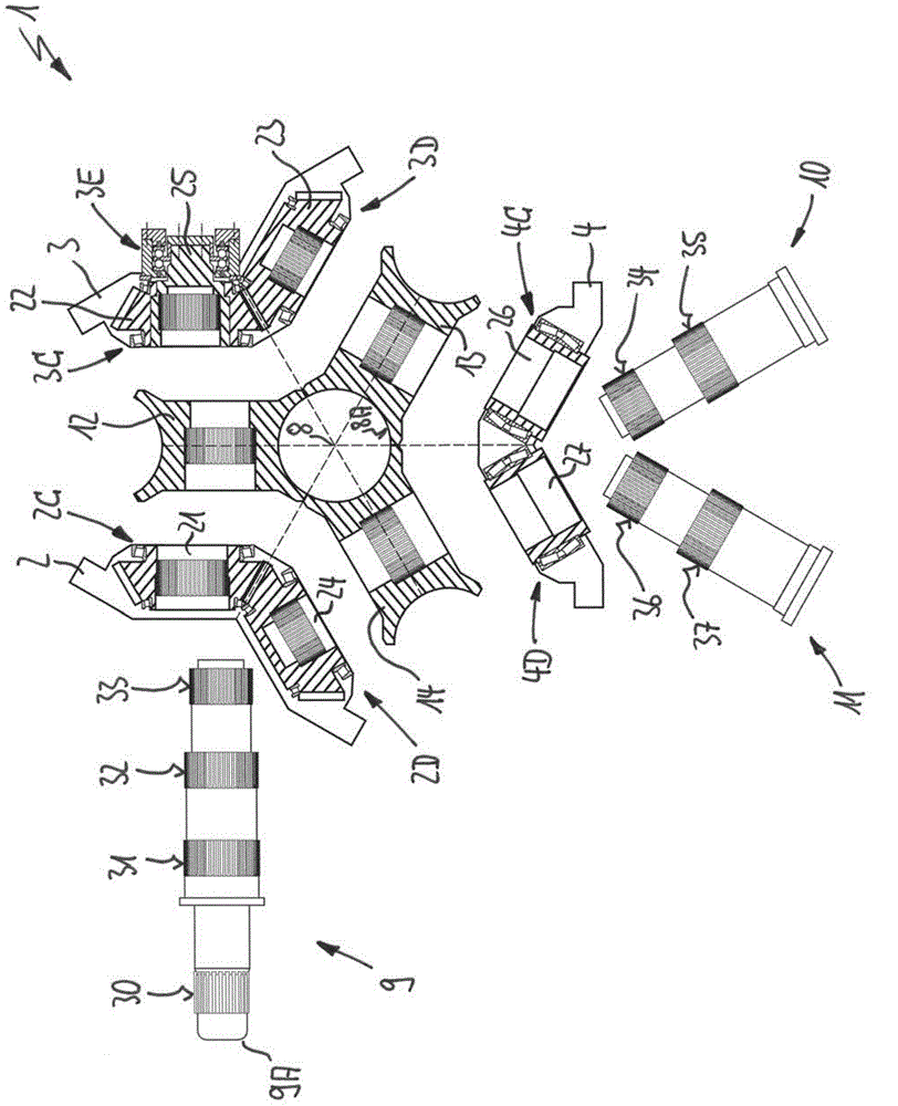
[0059] exist Figures 1 to 4 In the first exemplary embodiment shown, the roll stand 1 comprises a total of three stand bodies 2, 3 and 4, of which the three rolls 5, 6 and 7 surround a pass line 8 or axially extending processing section Mounted concentrically, the three rolls 5 , 6 and 7 thus form a rolling pass 8A for rolling rolling material not shown here.

[0060] Each roll 5, 6 and 7 comprises roll shafts 9, 10 and 11 and associated roll elements 12, 13 and 14, respectively, whereby these three roll elements 12, 13 and 14 form a rolling pass 8A, which especially in accordance with Figure 1 to Figure 3 shown in the illustration.

[0061] The frame bodies 2, 3 and 4 are constructed with respective angles such that they form respective bearing housings 2A, 2B, 3A, 3B, 4A and 4B for two of the three roller shafts 12, 13 and 14 respectively. indivual.

[0062] as from according to Figure 4 As particularly clearly visible in the illustration of , the first frame body 2 ...


PUM


Abstract

In order to simplify roll adjustment in a roll stand when changing the rolls, a roll stand absorbs rolling forces of at least three rolls mounted on both sides in bearing seats of the roll stand that absorb rolling forces, in each instance. At least the bearing seats of one roll are disposed in a stand body jointly with a bearing seat of another roll, in each instance. One of the stand bodies has fixed bearings of the two related rolls, in each instance, and / or one of the stand bodies has floating bearings of the two related rolls, in each instance.

Description

technical field [0001] The invention relates to a roll stand for absorbing rolling forces, wherein at least three rolls are mounted on both sides on corresponding bearing housings of the rolling force-absorbing roll stand, wherein for each case at least The chocks of one roll are provided in the frame body together with the chocks of the other roll. Background technique [0002] Roll stands of the stated type are well known in the state of the art and they have been used successfully for a long time in the rolling of elongated materials. In this respect, the roll stands can act as bearing frames in which the quick release roll shafts of the rolls can be mounted for rotation, whereby the roll elements fixed to these quick release roll shafts form elongated material through which Rolled center rolled pass opening. In this respect, a plurality of rolls, typically three or four rolls, are each arranged on a roll stand in one plane. In order to be able to roll the elongated ma...

Claims


Application Information

Patent Timeline
Patent Type & Authority Applications(China)
IPC IPC(8): B21B31/02
CPCB21B13/103B21B31/08B21B29/00B21B31/07
Inventor 约沃·苏巴诺维奇加夫列莱·菲滕沃尔特·霍夫根
Owner SMS MEER
Learn More