Plastic looping tool guide bar

A loop-forming tool and bar technology, applied in textiles and papermaking, knitting, warp knitting and other directions, can solve the problems of loop-forming tool collision, increased risk of loop-forming tool bar deformation, etc., and achieve the effect of stable structure

Active Publication Date: 2014-08-27
KARL MAYER STOLL R&D GMBH
View PDF10 Cites 4 Cited by
  • Summary
  • Abstract
  • Description
  • Claims
  • Application Information

AI Technical Summary

Problems solved by technology

This increases the risk of deformation of the looping tool bar
Such a deformation is in turn undesirable, since the deformation causes the loop forming tool fixed at the loop forming tool bar to no longer be in its desired position, so that collisions of the cooperating loop forming tools can occur in unfavorable situations

Method used


Image

  • Plastic looping tool guide bar
  • Plastic looping tool guide bar
  • Plastic looping tool guide bar

Examples


Embodiment Construction

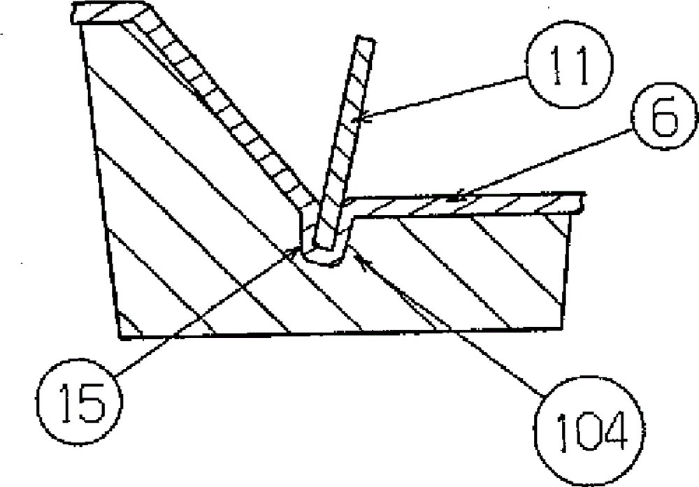
[0026] figure 1 The looping tool bar 1 is shown very schematically, which is mainly formed from plastic. The bar 1 has a body 2 with an upper wall 4 forming an upper side 3 and a lower wall 6 forming a lower side 5 . The terms “upper” and “lower” or “upper side” and “lower side” relate to the illustration in the figures and are chosen so that walls and sides can be distinguished in a simple manner. When the looping tool bar 1 is installed in the knitting machine, it does not necessarily give these relationships again. In this case, the looping tool bar 1 can be mounted rotated, for example, by 90° relative to the illustration in the drawing.

[0027] A receiving area 7 for a loop forming tool (not shown in detail) is provided on the main body 2 .

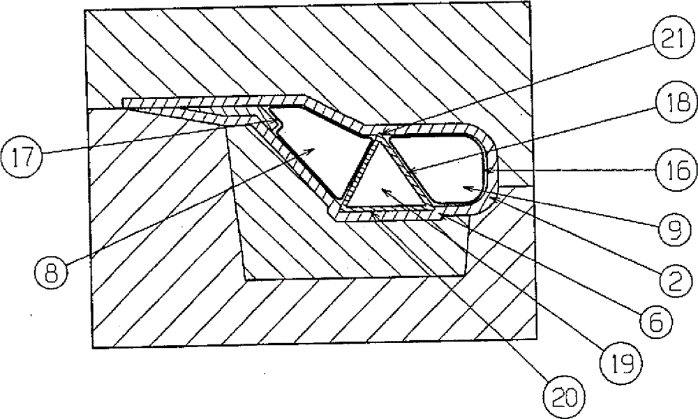
[0028] The main body 2 has a cavity assembly. In this embodiment, the cavity assembly has two cavities 8 , 9 . A reinforcement 10 is arranged between the two cavities 8 , 9 . In this embodiment, the reinforcement 10 has the fo...


PUM


Abstract

The invention relates to a plastic looping tool guide bar 1, which comprises a main body 2. The main body 2 comprises an upper wall 4 forming an upper side, a lower wall 6 forming a lower side and a hollow chamber assembly. It is desired to make the working speed of a warp knitting machine as high as possible. To the end, the hollow chamber assembly comprises at least two hollow chambers 8, 9 which are separated through a reinforcing part 10.

Description

technical field [0001] The invention relates to a plastic looping tool bar with a body having an upper wall forming an upper side, a lower wall forming a lower side and a cavity part. Background technique [0002] Such a loop forming tool bar and such a method are known from document EP 1 820 891 B1. In this, a planar semi-finished product is introduced into a press form, wherein a hose is inserted into the press form together in such a way that it is surrounded by the semi-finished product. If the die is then closed and the hose is put under pressure, the semifinished product is pressed against the die from the inside. Relatively large internal pressures can be generated using hoses. In a first approximation, it can be assumed that the strength of the body increases with pressure up to a certain limit, ie the greater the pressure, the greater the strength of the body. [0003] A further possibility for producing such a looping tool bar consists in forming the bar as a pr...

Claims


Application Information

Patent Timeline
IPC IPC(8): D04B27/24
CPCD04B27/06
Inventor M.肖尔莱默
Owner KARL MAYER STOLL R&D GMBH
Why Eureka
Try Eureka