Transmission-driving unit with electronic interface which can be locked

A drive unit and electronic interface technology, applied in the direction of electrical components, electric components, electromechanical devices, etc., can solve problems such as unproven intervention, and achieve the effect of saving parts and installation costs

Active Publication Date: 2016-02-10
ROBERT BOSCH GMBH
View PDF8 Cites 7 Cited by
  • Summary
  • Abstract
  • Description
  • Claims
  • Application Information

AI Technical Summary

Problems solved by technology

The disadvantage of this device is that the snap connection of the electronics interface can be released without damage at any time in order to open the

Method used


Image

  • Transmission-driving unit with electronic interface which can be locked
  • Transmission-driving unit with electronic interface which can be locked
  • Transmission-driving unit with electronic interface which can be locked

Examples


Embodiment Construction

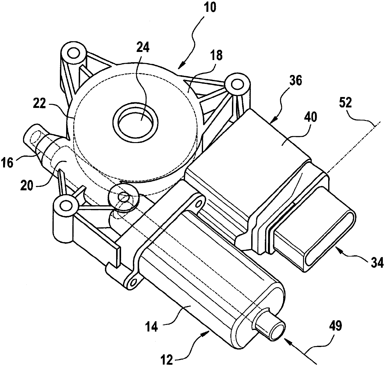
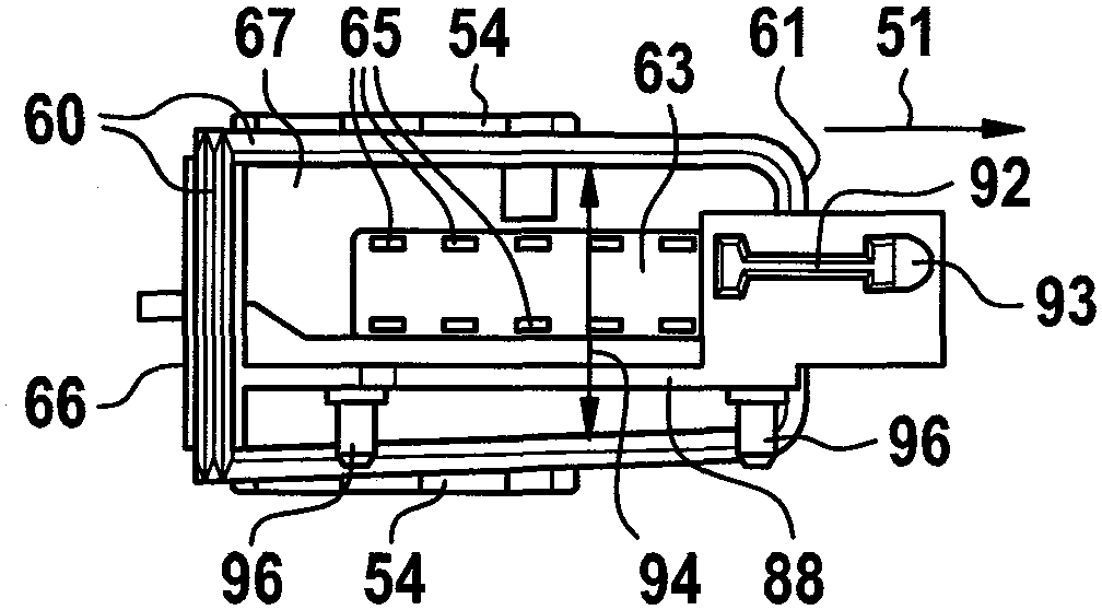
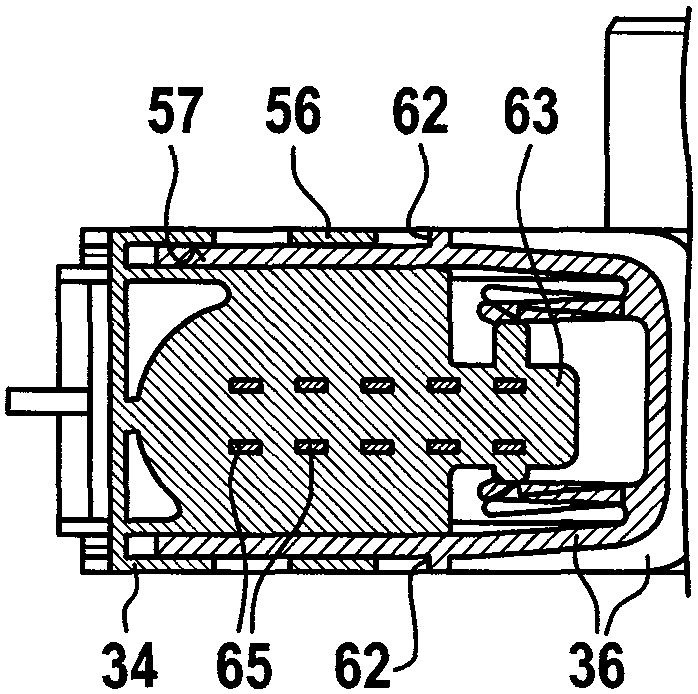
[0026] figure 1 and figure 2 The transmission drive unit 10 , in particular a transmission drive unit 10 for a window regulator, is shown after insertion of the electronics module 34 and before the insertion of the electronics module 34 . The rotor shaft 16 protrudes from the pole shoe 14 of the electric motor 12 into the transmission housing 18 . Arranged on the rotor shaft 16 is a worm 20 which meshes with a worm wheel 22 and transmits the force via a drive pinion 26 mounted on its shaft 24 to a window lifter (not shown in detail) Fensterhebermechanik). For detecting the position of the adjustable component, for example a ring magnet is arranged on the rotor shaft 16 in the region of the transmission housing 18 , which interacts with a Hall sensor 30 arranged on a printed circuit board 32 of an electronics module 34 . . For insertion of the electronics module 34 , the transmission drive unit 10 has an electronics interface 36 which is formed integrally with the transmis...


PUM


Abstract

Provided are a transmission-driving unit (10), and a method for manufacturing the transmission-driving unit. The transmission-driving unit comprises an electric motor (12) and transmission housings (14,18) with an electronic interface (36) which is used to hold an electronic module (34). The electronic module can be inserted into the electronic interface (36) along an insertion direction (51), and the electronic interface (36) has walls (38) which are separated. The wall and the electronic module (34) together form an electronic housing (40) used to seal an electronic element (33). The electronic interface (36) is provided with a locking element (76) and the electronic module (34) is provided with a corresponding pairing locking element (74). After the electronic module (34) is completely inserted, the locking element and the pairing locking element are mutually fixedly locked and are completely in the electronic housing (40).

Description

technical field [0001] The invention relates to a transmission-drive unit with an electronic interface and a method for connecting an electronic module to a transmission-drive unit of the type described in the independent claims. Background technique [0002] Various drives are already known in which a separate electronics module can be coupled to the housing of the drive. For example, DE 20004338 A1 shows a drive with an electric motor in a transmission housing into which a plug-in module can be plugged. The plug-in module has an end face with a plug on the outside and a printed circuit board on the inside, on which the motor contacts for the motor power supply and the electronic components are arranged. Arranged on the fingers of the printed circuit board are SMD Hall sensors which cooperate with the ring magnet of the armature shaft in the mounted state. [0003] EP 1 618 645 B1 discloses a drive unit in which a detent opening is formed on the outer side wall of the ele...

Claims


Application Information

Patent Timeline
IPC IPC(8): H02K11/00H02K5/22
Inventor L-D.安丁F.齐内格
Owner ROBERT BOSCH GMBH
Why Eureka
Try Eureka