

Straight rack driven different-speed linkage mechanism
A technology of linkage mechanism and straight rack, which is applied in the direction of mechanical equipment, transmission devices, friction transmission devices, etc., can solve the problems of high cost of power source procurement and use, poor reliability of mechanism linkage action, complex control system, etc., and achieve convenient automation Control, low cost, small size effect
- Summary
- Abstract
- Description
- Claims
- Application Information
AI Technical Summary
Problems solved by technology
Method used
Image

Examples
Embodiment Construction
[0013] The present invention and its beneficial technical effects will be further described in detail below in conjunction with the accompanying drawings and preferred embodiments.
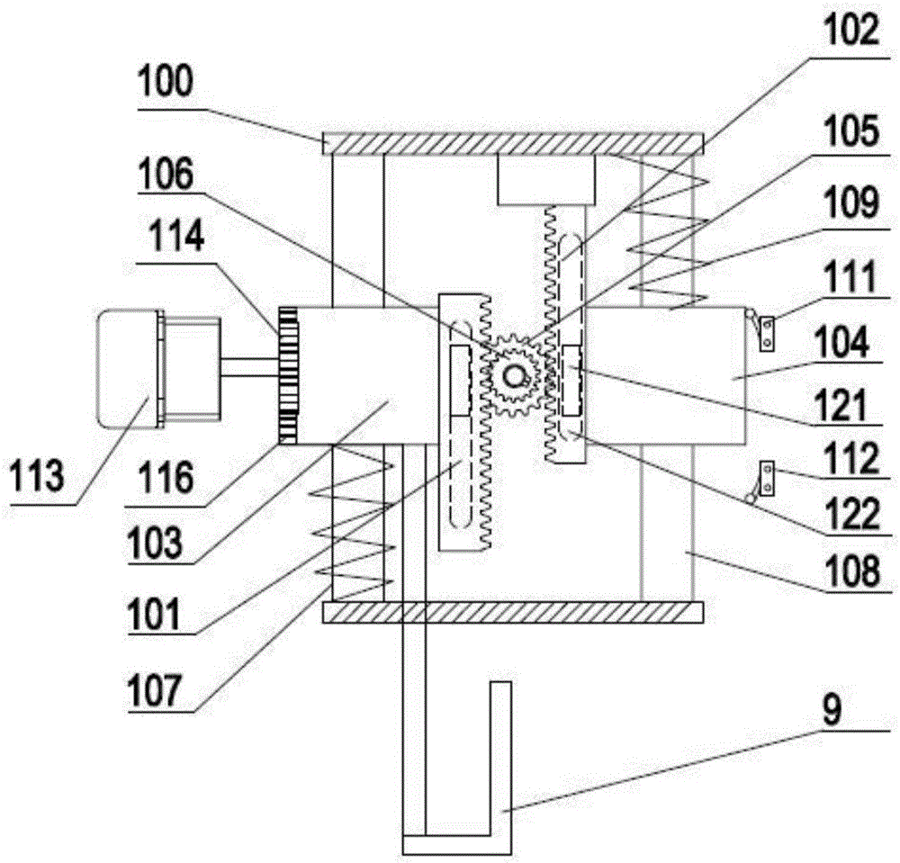
[0014] see figure 1 , as can be seen from the figure, the different-speed linkage mechanism driven by the spur rack 116 includes the installation frame 100, and the power source fixed on the installation frame 100; Driven guide rail 108; Active guide rail 107 and driven guide rail 108 are provided with slide block, are respectively active slide block 103 and driven slide block 104; The racks are the driving rack 101 and the driven rack 102 respectively, and the pitches of the driving rack 101 and the driven rack 102 are different; a rotatable Linkage gears, the gears are arranged on the installation frame 100 through bearings; the driving rack 101 and the driven rack 102 are meshed with the linkage gears respectively; the power source is the rack transmission assembly installed on the outside of ...
PUM
 Abstract
Description
Claims
Application Information