
Laminating device and integrated die laminating device

A lamination device and lamination technology, applied in transportation and packaging, sustainable manufacturing/processing, electrochemical generators, etc., can solve the problems of low feeding rate, high labor intensity, low defect rate, etc., and achieve efficient operation , improve the lamination quality and reduce the defect rate

Pending Publication Date: 2019-11-22
哈工大机器人(中山)无人装备与人工智能研究院
View PDF9 Cites 11 Cited by
  • Summary
  • Abstract
  • Description
  • Claims
  • Application Information

AI Technical Summary

Problems solved by technology

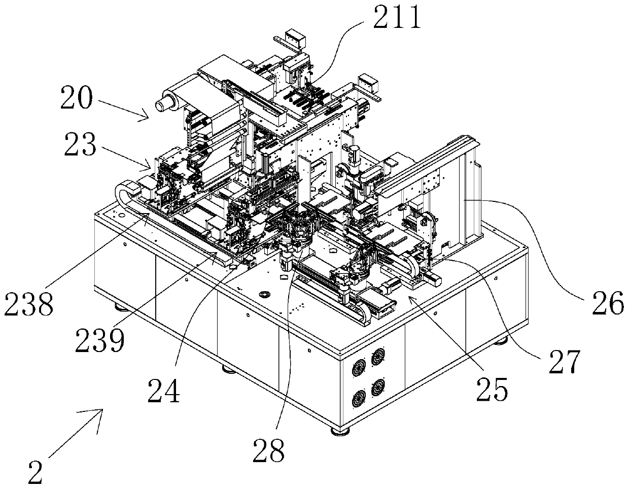
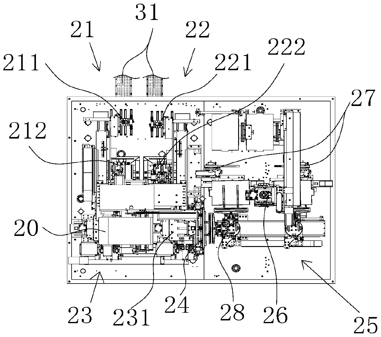
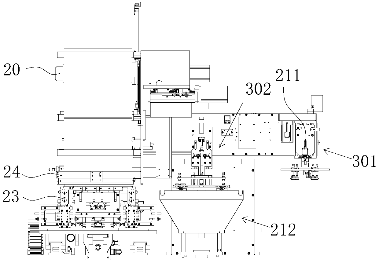
[0004] In view of the above problems, the object of the present invention is to provide a lamination device and an integrated die lamination device, which uses a pole piece die-cutting device to cooperate with an automatic lamination device to realize efficient operations of automatic feeding of pole pieces and integration of automatic lamination, and overcomes the The existing defects of manual feeding, low feeding rate and high labor intensity of loading; adopt efficient and accurate lamination coordination settings, so that the pole piece feeding mechanism and diaphragm conveying mechanism can cooperate with the lamination mechanism to perform stable and efficient lamination, improving The quality of cell lamination ensures low defect rate, and at the same time, through the new lamination structure, the lamination efficiency is effectively improved, the production input cost is reduced, the operation time is shortened, and the modern automatic production requirements of die-cutting, feeding, and lamination integration are realized.

Method used


Image

  • Laminating device and integrated die laminating device
  • Laminating device and integrated die laminating device
  • Laminating device and integrated die laminating device

Examples


Embodiment Construction

[0074] In order to make the object, technical solution and advantages of the present invention clearer, the present invention will be further described in detail below in combination with specific embodiments and with reference to the accompanying drawings. It should be understood that these descriptions are exemplary only, and are not intended to limit the scope of the present invention. Also, in the following description, descriptions of well-known structures and techniques are omitted to avoid unnecessarily obscuring the concept of the present invention.

[0075] Embodiments of the present invention are described in detail below, examples of which are shown in the drawings, wherein the same or similar reference numerals represent the same or similar elements or elements having the same or similar functions throughout.

[0076] In the description of the present invention, it should be noted that for orientation words, such as the term "center", "horizontal", "longitudinal", ...


PUM


Abstract

The invention discloses a laminating device. The laminating device comprises a diaphragm conveying mechanism for discharging and conveying rolled diaphragms; a positive electrode feeding mechanism which is used for continuously conveying single positive electrode plates; a negative electrode feeding mechanism which is used for continuously conveying single negative electrode plates; a laminating mechanism which reciprocates between the positive electrode feeding mechanism and the negative electrode feeding mechanism and receives the diaphragms, the positive electrode plates and the negative electrode plates, so that the diaphragms are pressed on the laminating mechanism and then move along with the laminating mechanism to form a Z-shaped diaphragm, wherein the positive electrode plates andthe negative electrode plates are alternately laminated on the Z-shaped diaphragm to form a Z-shaped laminated sheet; a diaphragm cutting mechanism which is used for cutting off the diaphragm supplyof the diaphragm conveying mechanism to the laminating mechanism after the laminating mechanism finishes laminating; and a rubberizing mechanism which is used for rubberizing the Z-shaped laminated sheet to form a battery cell. The defects of low speed and high labor intensity of manual feeding are overcome, the production cost is reduced, the lamination efficiency is improved, and modern automatic production integrated with die cutting and lamination is realized.

Description

technical field [0001] The invention relates to the technical field of pole piece processing, in particular to a lamination device and an integrated die lamination device using the lamination device. Background technique [0002] Lithium-ion batteries use carbon materials as negative electrodes and lithium-containing compounds as positive electrodes. Lithium-ion batteries are secondary batteries (rechargeable batteries), which mainly rely on lithium ions to move between the positive and negative electrodes to work. Due to the stacked structure of the lithium-ion battery cell, when laminating, the current pole piece feeding method needs to manually transport the die-cut pole piece to the stacking level. The production input cost of the material method is high and the feeding rate is low, which affects the accuracy of the lamination; moreover, the existing pole piece feeding device can only feed two materials to one lamination device, resulting in low production efficiency and...

Claims


Application Information

Patent Timeline
Patent Type & Authority Applications(China)
IPC IPC(8): H01M10/0583B65H29/16
CPCH01M10/0583B65H29/16Y02E60/10Y02P70/50
Inventor 刘一磊张磊王洪波
Owner 哈工大机器人(中山)无人装备与人工智能研究院
Learn More