Electric press device

A technology of electric stamping and electric motors, which is applied in the direction of stamping machines, presses, manufacturing tools, etc., and can solve problems such as inability to implement fixed-point processing

Inactive Publication Date: 2007-01-31
INST OF TECH PRECISION ELECTRICAL DISCHARGE WORKS
View PDF2 Cites 8 Cited by
  • Summary
  • Abstract
  • Description
  • Claims
  • Application Information

AI Technical Summary

Problems solved by technology

[0011] Due to the displacement of the movable body 50, the initial height H of the push member 91 0 Of course, it also changes, but when the screw shaft 40 is rotated in this state, the predetermined fixed-point machining cannot be performed.

Method used


Image

  • Electric press device
  • Electric press device
  • Electric press device

Examples


Embodiment 1

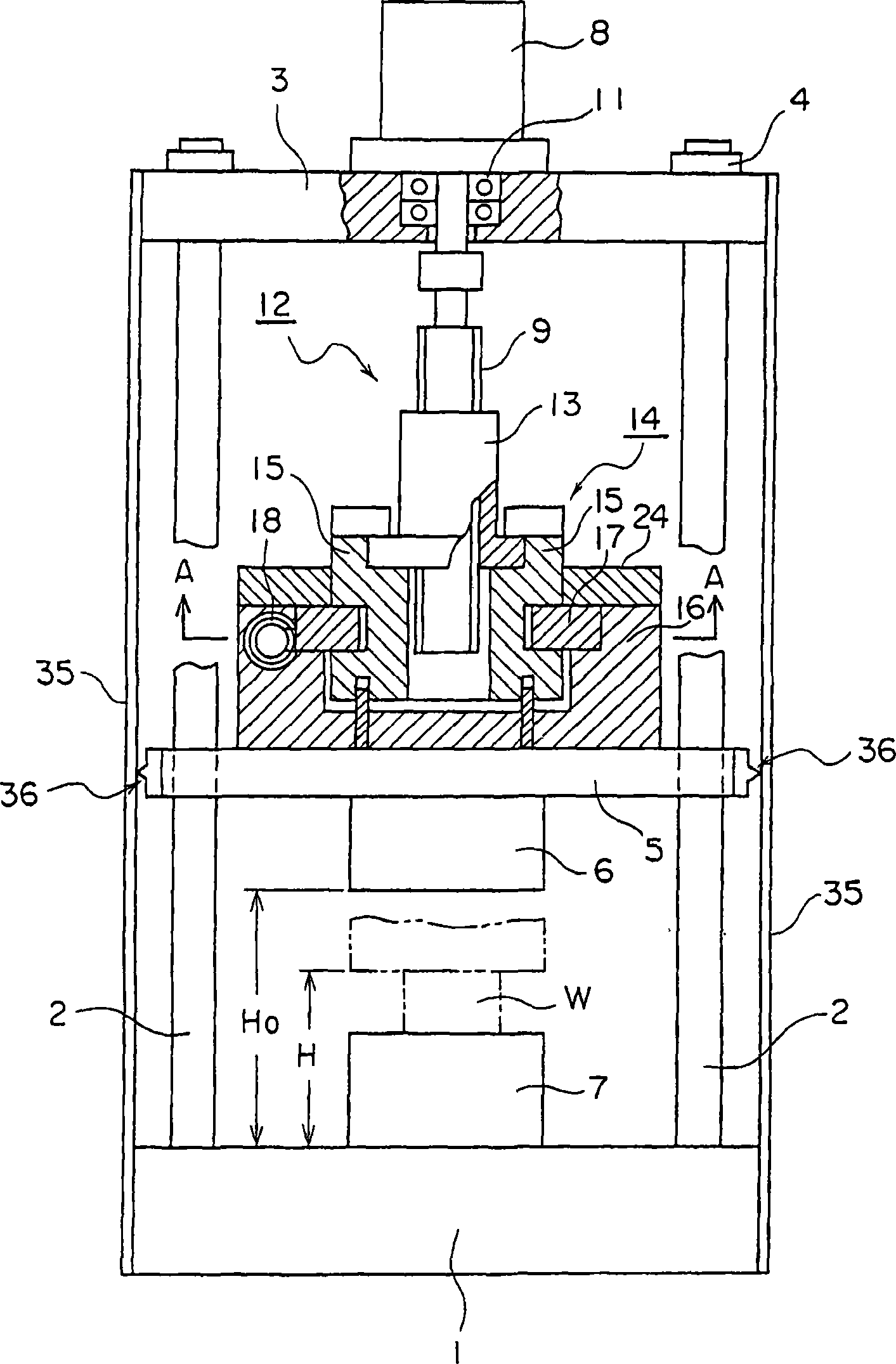
[0051] figure 1 It is a front view of an embodiment in which a part of the main part of the electric press device of the present invention is in cross section.

[0052] exist figure 1 In the figure, reference numeral 1 is a substrate, which is formed in, for example, a rectangular flat plate, and columnar guide rods (guide bodies) 2 are erected at four corners thereof. A rectangular flat support plate 3 is fixed to an upper end portion of the guide rod 2 via a connecting member 4 .

[0053] Symbol 5 is a sliding plate, which is slidably engaged with the guide rod 2 and can be slid up and down, and the push piece 6 is fixed at the bottom. Reference numeral 7 denotes a table, which is provided on the substrate 1 and on which the workpiece W is placed.

[0054] A motor (first motor) 8 with a built-in encoder is provided on the support plate 3, and a ball screw shaft 9 is freely rotatably connected to its shaft via a thrust bearing 11 provided on the support plate 3. The ball...

Embodiment 2

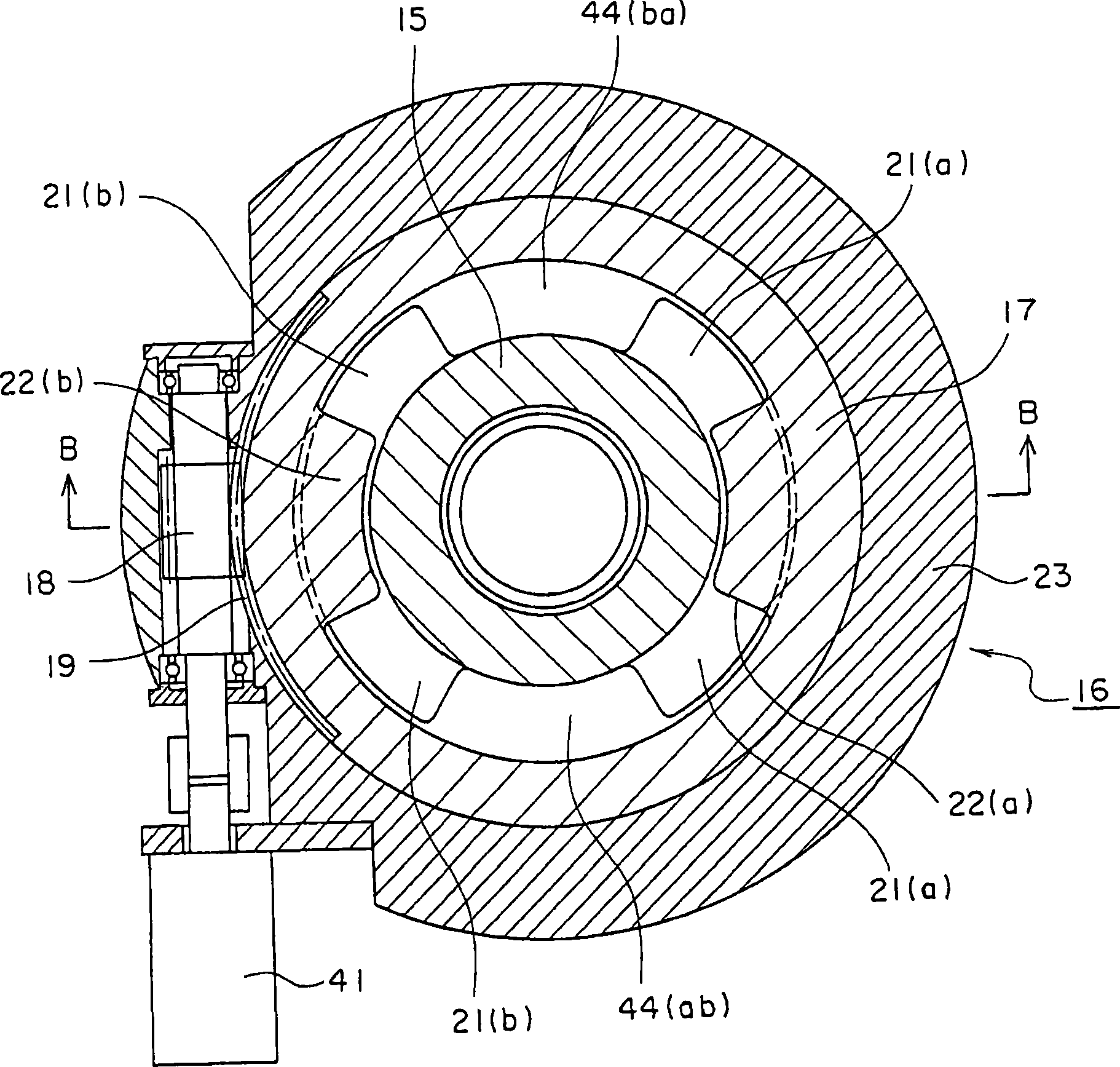
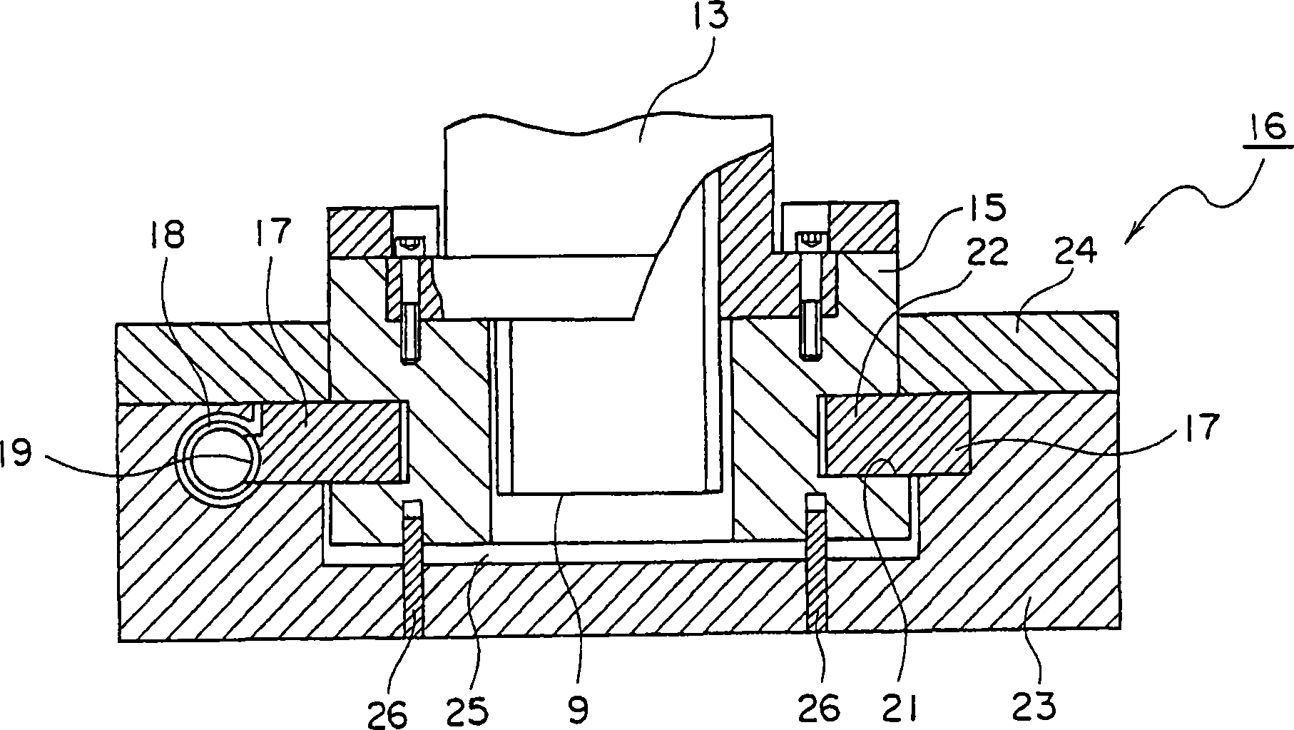
[0059] figure 2 with image 3 A detailed diagram showing the differential mechanism, figure 2 for figure 1 A-A direction view, image 3 for figure 2 B-B direction view. The symbols in the figure and figure 1 correspond.

[0060] A worm gear 19 that meshes with a worm 18 provided in the storage body 16 is provided on the nut lifting plate 17 . In addition, a helical sliding groove 21 (refer to FIG. 5 which exaggerates the angle of the sliding groove 21 ) is formed at the central part of the outer peripheral surface of the nut lifting sleeve 15 , and on the inner periphery of the nut lifting plate 17 A guide engaging portion 22 (refer to FIG. 5 exaggerating the angle of the guide engaging portion 22 ) is provided on the surface, and the guide engaging portion 22 is slidably engaged with the slide groove 21 running in a helical shape of the nut elevating sleeve 15 .

[0061] The housing 16 is formed by a housing member 23 and a ring member 24. The housing member 23 s...

Embodiment 3

[0088] Figure 15 with Figure 16 Another embodiment of the differential mechanism is shown, Figure 15 for with image 3 corresponding figure, Figure 16 for with figure 2 corresponding figure.

[0089] Symbol numbers 9, 13 (15), 17, 18, 19, 21, 22, 23, 24, 26, 44 and figure 2 or image 3 correspond.

[0090] exist Figure 15 with Figure 16 case of the example shown, with figure 2 with image 3 Compared with the illustrated embodiment, the difference is actually the following two points.

[0091] one of which is figure 2 with image 3 The shown nut member 13 is constructed as one piece with the nut lifter sleeve 15 . where the second point is with figure 2 with image 3 There are three guide joints corresponding to the guide joints 22 of the nut lifting plate 17 at intervals of 120°, and there are three cutouts corresponding to the cutouts 44 of the nut lifter sleeve 15 at intervals of 120°. The sliding groove corresponding to the groove 21 is divided i...


PUM


Abstract

An electric press device formed in such a structure that a differential key is circumferentially moved in place of such a structure in a publicly known document that a differential key is linearly moved so that a fixed point processing requiring accurate position control can be accurately performed for a long time. A slide plate (5) is vertically moved by a first motor (8) to process a work at a fixed position. A differential mechanism comprises a cylindrical nut lifting sleeve (15) having a spirally advancing sliding groove (21) in the outer peripheral surface thereof, a nut lifting plate (17) having a guiding engagement part (22) fitted to the sliding groove and allowed to slide therein, and a second motor (41) rotating the nut lifting plate (17).

Description

technical field [0001] The present invention relates to an electric punching device used, for example, in sheet metal processing, and more particularly, to an electric punching device in which a ball screw shaft is driven by an electric motor, and a ball screw shaft is driven by a ball screw shaft and its nut portion. The lever engagement makes the push member reciprocate, for example, move up and down, and by such a mechanism, fixed-point machining requiring accurate position control in units of micrometers is performed. Background technique [0002] In the prior art electric press device, the ball screw shaft is driven by an electric motor, and the push member is moved up and down by engaging the ball screw shaft with the ball screw on the nut portion. As such a prior art electric press device, the applicant Electric press devices described in Patent Document 1 and Patent Document 2 have been proposed. [0003] Figure 17 It is a front view of the longitudinal section of ...

Claims


Application Information

Patent Timeline
Patent Type & Authority Applications(China)
IPC IPC(8): B30B15/06B30B1/18
CPCB30B15/0035B30B15/041B30B1/18B30B1/186Y10S100/00
Inventor 二村昭二海野敬三
Owner INST OF TECH PRECISION ELECTRICAL DISCHARGE WORKS
Why Eureka
Try Eureka