Solar air heating collector

An air collector and solar energy technology, which is applied in the field of solar energy utilization, can solve the problems that the solar radiation heat cannot be fully utilized, it is difficult to increase the air temperature at the outlet end of the collector, and the application of the air collector is limited, so as to improve the heat collection efficiency. effect, prevention of convection exchange, energy saving effect

Inactive Publication Date: 2014-08-27
CHANGZHOU SUNLIGHT SOLAR ENERGY
View PDF3 Cites 5 Cited by
  • Summary
  • Abstract
  • Description
  • Claims
  • Application Information

AI Technical Summary

Problems solved by technology

[0002] Most of the existing solar air collectors are flat-plate structures, and the temperature rise of the air is low in the case of good light, and the highest can only reach about 26 degrees. Although there have been structural improvements since then, such as adding air Heating paths, filling heat storage materials, etc., but it is still difficult to increase the air temperature at the outlet end of the collector, which limits the application of air collectors
Later, a structure using vacuum tubes for heat collection also appeared. The vacuum tubes used are open-ended vacuum tubes. Cold air enters from one end of the vacuum tube, receives solar radiation in the vacuum tube, and the heated hot air is discharged from the other end of the vacuum tube. It is a blind tube with one end open and one end closed, and it is mostly used for flow heating of liquid medium. The existing vacuum tube heat collector structure is difficult to apply, and the existing vacuum tube air collector, cold air is directly discharged through the vacuum tube. Its flow path is still limited by the length of the vacuum tube, the temperature of the discharged hot air is not very high, and the heat of solar radiation cannot be fully utilized

Method used


Image

  • Solar air heating collector
  • Solar air heating collector

Examples


Embodiment Construction

[0012] The present invention will now be further described in conjunction with the accompanying drawings and preferred embodiments. These drawings are all simplified schematic diagrams, which only illustrate the basic structure of the present invention in a schematic manner, so they only show the configurations related to the present invention.

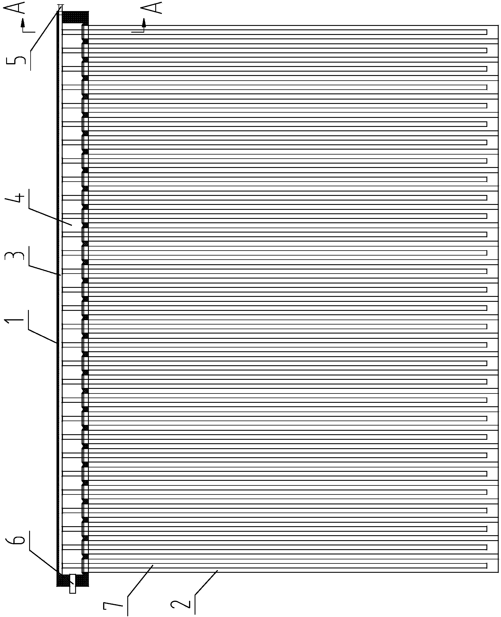
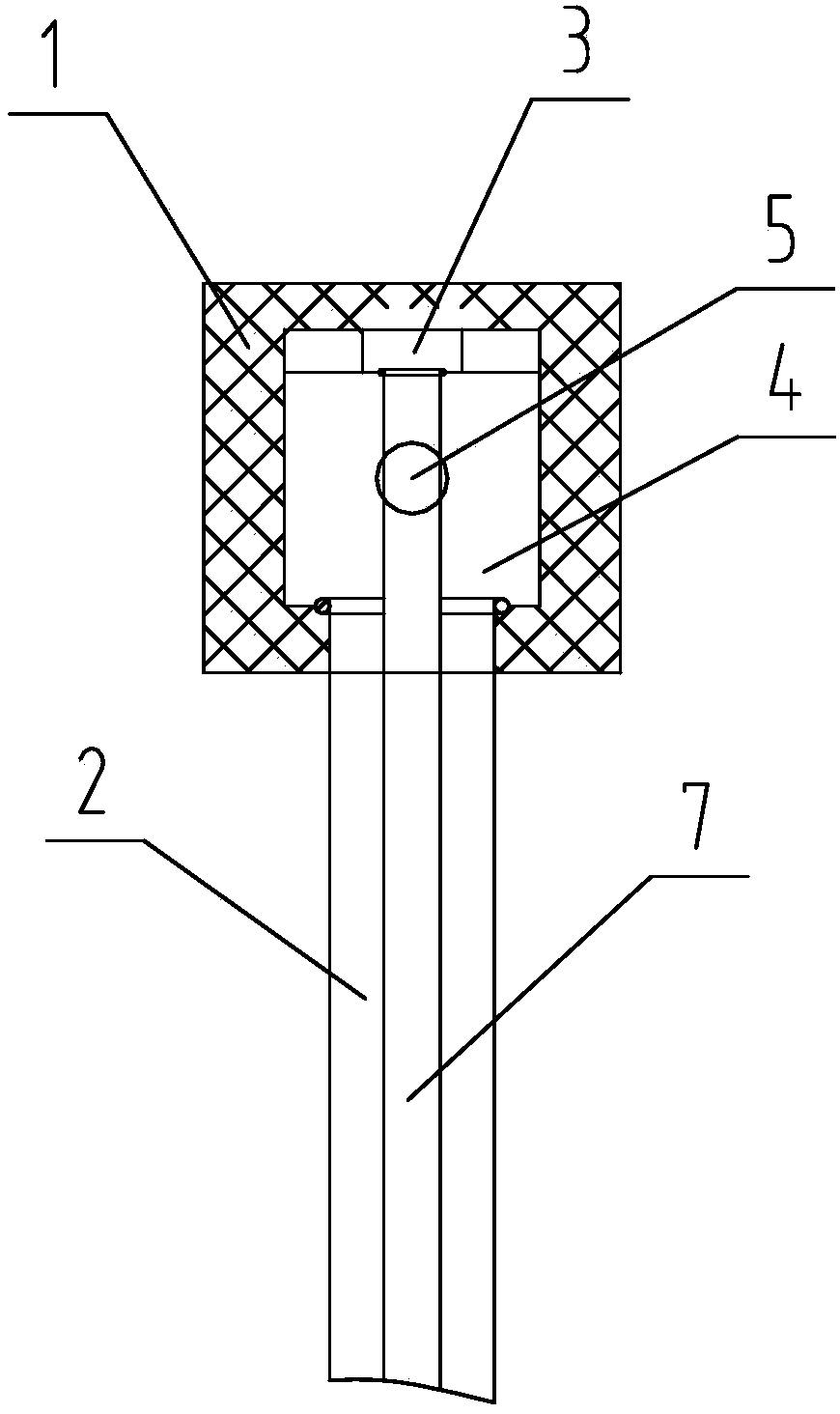
[0013] Such as figure 1 , figure 2 A solar air heat collector is shown, which uses solar radiation to heat air and is applied to heating, drying, drying and other hot air application systems, including an air header 1 and vacuum tubes 2 for absorbing solar radiation heat, thirty pieces The vacuum tubes 2 are arranged equidistantly in sequence perpendicular to the axis of the air header 1 , and the assembled air header 1 and vacuum tubes 2 are installed on an inclined bracket that can absorb more sunlight and has a suitable installation angle.

[0014] The vacuum tube 2 is a blind tube with an open upper end and a closed lower end. ...


PUM


Abstract

The invention discloses a solar air heating collector which comprises an air header and vacuum tubes perpendicular to the axis of the air header. Each vacuum tube is a blind tube with open end and the other closed end, cold air flowing channels and hot air flowing channels parallelly arranged and spaced are arranged in the air header, air inlet tubes communicated with the cold air flowing channels and air outlet tubes communicated with the hot air flowing channels are arranged on the air header, the open ends of the vacuum tubes are in sealed connection with the outer wall of the air header and then is communicated with the hot air flowing channels, a cold air guide tubes with two open ends are arranged in each vacuum tube, one end of each cold air guide tube is close to the closed end of the corresponding vacuum tube, the other end of each cold air guide tube is communicated with the corresponding cold air flowing channel. By arranging the cold air guide tubes in the common vacuum tubes and utilizing the vacuum tubes to absorb solar radiation energy and collect heat, hot air is discharged through exchange with cold air pressed by a fan, so that cold air can obtain much heat and accordingly can be heated, the solar energy heat is fully utilized, the heat collecting effect is improved, energy is saved, and the using cost is reduced.

Description

technical field [0001] The invention relates to the technical field of solar energy utilization, in particular to a solar air heat collector applicable to heating, drying, drying and other hot air application systems. Background technique [0002] Most of the existing solar air collectors are flat-plate structures, and the temperature rise of the air is low in the case of good light, and the highest can only reach about 26 degrees. Although there have been structural improvements since then, such as adding air Heating paths, filling heat storage materials, etc., but it is still difficult to increase the air temperature at the outlet end of the collector, which limits the application of air collectors. Later, a structure using vacuum tubes for heat collection also appeared. The vacuum tubes used are open-ended vacuum tubes. Cold air enters from one end of the vacuum tube, receives solar radiation in the vacuum tube, and the heated hot air is discharged from the other end of t...

Claims


Application Information

Patent Timeline
Patent Type & Authority Applications(China)
IPC IPC(8): F24J2/24F24S10/70
CPCY02E10/44
Inventor 梅建中
Owner CHANGZHOU SUNLIGHT SOLAR ENERGY
Why Eureka
Try Eureka