A slope optical fiber Bragg grating multi-point displacement sensor and its application method

A technology of displacement sensor and optical fiber, applied in instruments, optical devices, measuring devices, etc., to achieve strong corrosion resistance, easy operation, and simple structure

Inactive Publication Date: 2016-09-21
KUNMING UNIV OF SCI & TECH
View PDF5 Cites 0 Cited by
  • Summary
  • Abstract
  • Description
  • Claims
  • Application Information

AI Technical Summary

Problems solved by technology

[0004] The invention provides a slope optical fiber Bragg grating multi-point displacement sensor and its use method to solve the problem of real-time online detection of slope multi-point displacement

Method used


Image

  • A slope optical fiber Bragg grating multi-point displacement sensor and its application method
  • A slope optical fiber Bragg grating multi-point displacement sensor and its application method
  • A slope optical fiber Bragg grating multi-point displacement sensor and its application method

Examples


Embodiment 1

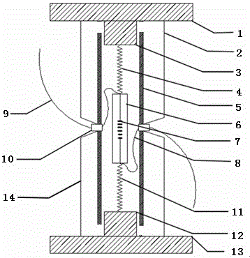
[0049] Embodiment 1: as Figure 1-5 As shown, a slope optical fiber Bragg grating multi-point displacement sensor includes an upper flange 1, an upper elastic protection ring 2, an upper pull rod 3, an upper displacement spring 4, a protective steel pipe 5, an elastic steel sheet 6, and an optical fiber Bragg grating 7. The lower connected optical fiber 8, the upper connected optical fiber 9, the steel pipe optical fiber outlet hole 10, the lower end displacement spring 11, the lower end pull rod 12, the lower end flange 13, and the lower end elastic protection ring sleeve 14; wherein the base of the upper end pull rod 3 is tapped and The upper flange 1 is connected, the other end of the upper pull rod 3 is connected with one end of the upper displacement spring 4, the other end of the upper displacement spring 4 is connected with the elastic steel sheet 6, and the optical fiber Bragg grating 7 is pasted on the elastic steel sheet 6, and the elastic steel The lower end of shee...

Embodiment 2

[0057] Embodiment 2: as Figure 1-5 As shown, a slope optical fiber Bragg grating multi-point displacement sensor includes an upper flange 1, an upper elastic protection ring 2, an upper pull rod 3, an upper displacement spring 4, a protective steel pipe 5, an elastic steel sheet 6, and an optical fiber Bragg grating 7. The lower connected optical fiber 8, the upper connected optical fiber 9, the steel pipe optical fiber outlet hole 10, the lower end displacement spring 11, the lower end pull rod 12, the lower end flange 13, and the lower end elastic protection ring sleeve 14; wherein the base of the upper end pull rod 3 is tapped and The upper flange 1 is connected, the other end of the upper pull rod 3 is connected with one end of the upper displacement spring 4, the other end of the upper displacement spring 4 is connected with the elastic steel sheet 6, and the fiber Bragg grating 7 is pasted on the elastic steel sheet 6, and the elastic steel The lower end of sheet 6 is c...


PUM

PropertyMeasurementUnit
wavelengthaaaaaaaaaa
Sensitivityaaaaaaaaaa

Abstract

The invention relates to a slope optical fiber Bragg grating multi-point displacement sensor and a using method thereof, which belong to the technical field of optoelectronic measurement. The invention includes an upper end flange, an upper end elastic protection ring sleeve, an upper end pull rod, an upper end displacement spring, a protective steel pipe, an elastic steel sheet, an optical fiber Bragg grating, an optical fiber leading out from a lower connection, an optical fiber leading out from an upper connection, a steel pipe optical fiber extraction hole, and a lower displacement spring , the lower tie rod, the lower flange, and the lower elastic protective ring; according to the shift value of the center wavelength of the fiber Bragg grating pasted on the elastic steel sheet with sensor displacement Calculate the displacement change of the measurement position caused by the displacement of the soil layer of the slope hole or the cracking of the rock layer. The invention can connect different numbers of displacement sensors in series to realize multi-point displacement monitoring of slope holes according to different monitoring requirements; adopting the optical fiber Bragg grating has strong anti-electromagnetic interference ability and corrosion resistance; the structure is simple and easy to operate.

Description

technical field [0001] The invention relates to a side slope optical fiber Bragg grating multi-point displacement sensor and a using method thereof, belonging to the technical field of optoelectronic measurement. Background technique [0002] my country is a mountainous country, and the mountainous area accounts for about 2 / 3 of the country's total area. It is one of the countries with frequent landslides in the world. The landslide activity is related to the composition material, mechanical properties, shape, stratification, weak surface, structural surface and other factors of the landslide body, and the mechanism is relatively complicated. Internal displacement monitoring of slopes has always been an important topic concerned by geotechnical engineering circles. For the monitoring of deep displacement of rock and soil, sensors such as bedrock displacement gauges and multi-point displacement gauges are generally used. The sensing unit is installed at the position of the o...

Claims


Application Information

Patent Timeline
Patent Type & Authority Patents(China)
IPC IPC(8): G01B11/02
Inventor 谢涛李川李英娜赵振纲欧阳鑫刘爱莲吴文兵
Owner KUNMING UNIV OF SCI & TECH
Why Eureka
Try Eureka