Method for object marking using a three-dimensional surface inspection system using two-dimensional recordings and system

A surface detection, 3D technology, applied in measuring devices, image communication, using optical devices, etc., can solve problems such as complex internal structures, and achieve the effect of simple operation and accurate measurement

Inactive Publication Date: 2014-08-27
SIEMENS AG
View PDF17 Cites 12 Cited by
  • Summary
  • Abstract
  • Description
  • Claims
  • Application Information

AI Technical Summary

Problems solved by technology

But due to the complex internal structure (due to the internal heat sink), it is mandatory to position the sensor precisely (roughly 1mm) when measuring the wall thickness

Method used


Image

  • Method for object marking using a three-dimensional surface inspection system using two-dimensional recordings and system
  • Method for object marking using a three-dimensional surface inspection system using two-dimensional recordings and system
  • Method for object marking using a three-dimensional surface inspection system using two-dimensional recordings and system

Examples


Embodiment Construction

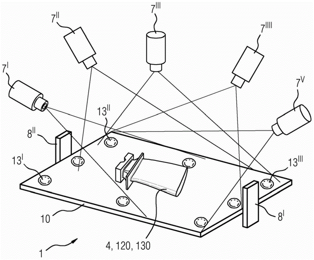
[0016] figure 1 A 3D surface inspection system 1 is shown.

[0017] The 3D surface inspection system 1 has a measuring table 10 on which a component 4 , 120 , 130 to be inspected is located.

[0018] Around the component 4, 120, 130 there is at least one camera 7', the position of which camera is changed or a plurality of preferably fixedly mounted cameras 7', ..., 7 are used V ,…….

[0019] The cameras 7', 7" are arranged in such a way that they detect the entire surface of the component 4, 120, 130 facing away from the measuring table 10.

[0020] The installation of the cameras 7', 7", ... can vary according to the type of part. For different sizes, types of turbine blades 120, 130 (rotor blades 120 or guide vanes 130) the installation of the cameras 7', 7", ... can be applied Same, fixed installation.

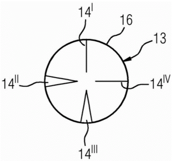
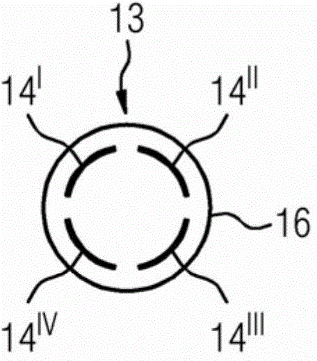
[0021] in accordance with figure 1 There is preferably at least one reference mark 13', 13", ... (as in Figure 2 to Figure 6 shown in ), where there are preferably...


PUM


Abstract

Method for object marking using a three-dimensional surface inspection system using two-dimensional recordings and method by simple recording of two-dimensional images of a component and comparing the images with a known three-dimensional model for enabling the three-dimensional real structure of a component to be captured using best fit. Photographing measuring points in a measuring point pattern and orienting the component with reference to markers at the points enables orienting the two-dimensional images with the three-dimensional model.

Description

technical field [0001] The invention relates to a method for object marking by means of a 2D photograph by means of a 3D surface detection system. Background technique [0002] In many components, 100% optical inspection of the entire three-dimensional component surface is required. This includes, for example, the position of the cooling air holes and the complete coating in the case of a turbine blade. [0003] Known three-dimensional inspection systems are very time-consuming and expensive. [0004] When measuring the wall thickness of hollow components with complex geometries (as in the case of turbine blades), it is difficult to find a predetermined measuring position, since there is no reference surface in any respect. But due to the complex internal structure (due to the internal cooling fins), it is mandatory to position the sensor exactly (approximately 1 mm) when measuring the wall thickness. [0005] During such a manual inspection, the component has to be moved...

Claims


Application Information

Patent Timeline
Patent Type & Authority Applications(China)
IPC IPC(8): G01B11/06G01B11/00G01B11/24
CPCG01B11/24G01B11/25H04N7/181
Inventor 罗尼·扬克特里斯坦·施策普雷克
Owner SIEMENS AG
Why Eureka
Try Eureka