A metal pipe stretching device

A technology of metal pipes and stretching devices, applied in the direction of applying stable tension/pressure to test the strength of materials, can solve problems such as low efficiency and inconvenient operation, and achieve the effect of preventing damage and offsetting displacement

Inactive Publication Date: 2016-02-17
BEIJING INSTITUTE OF TECHNOLOGYGY
View PDF7 Cites 0 Cited by
  • Summary
  • Abstract
  • Description
  • Claims
  • Application Information

AI Technical Summary

Problems solved by technology

[0007] The present invention solves the problem of inconvenient operation and low efficiency caused by the defect that the tensile testing machine in the prior art has no clamps for fixing cylindrical metal pipe specimens and cannot be used in combination with other loading devices. Further provide a stretching device that is easy to operate, simple and efficient, and can be used in conjunction with a pressure injection device

Method used


Image

  • A metal pipe stretching device
  • A metal pipe stretching device
  • A metal pipe stretching device

Examples


Embodiment 1

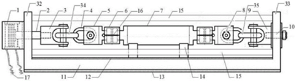
[0038] The metal pipe stretching device described in this embodiment includes: an assembly bracket 11 and a stretching structure, wherein: the assembly bracket 11 is formed with a first support plate 32 and a second support plate 33 arranged parallel to each other;

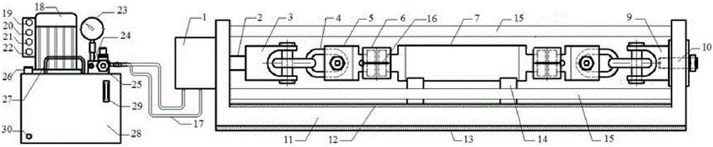
[0039] The tensile structure is arranged between the first support plate 32 and the second support plate 33, and includes a first connecting rod 34, a second connecting rod 35, a first buffer member and a second buffer member, wherein the first A connecting rod 34 is connected to the first support plate 32, and the second connecting rod 35 is connected to the second support plate 33. At the same time, the first connecting rod 34 is also connected to the hydraulic system, which is suitable for Under the action of the hydraulic system, the hydraulic system reciprocates in the axial direction. The hydraulic system in this embodiment includes a hydraulic cylinder 1 and a hydraulic connecting rod 2. The hydraulic cylind...

Embodiment 2

[0050] For the metal pipe stretching device described in this embodiment, see figure 1 ( figure 1 It is a schematic cross-sectional structure diagram of the metal pipe stretching device according to the present invention), including: an assembly bracket 11 and a stretching structure, wherein: the assembly bracket 11 is formed with a rectangular first support plate 32 and a second rectangular support plate arranged parallel to each other. Two support plates 33;

[0051] The tensile structure is arranged between the first support plate 32 and the second support plate 33, including: a first connecting rod 34, a second connecting rod 35, a first buffer member and a second buffer member, wherein the The first connecting rod 34 is connected to the first support plate 32, the second connecting rod 35 is connected to the second support plate 33, and the first connecting rod 34 is also connected to the hydraulic system. The hydraulic system reciprocates axially under the action of th...


PUM

PropertyMeasurementUnit
lengthaaaaaaaaaa

Abstract

The invention discloses a metal pipe stretching device. The metal pipe stretching device comprises an assembling support and a stretching structure, wherein the stretching structure comprises a first connecting rod, a second connecting rod, a first buffer element and a second buffer element; the first buffer element and the second buffer element respectively comprise an annular buffer structure and a buffer joint; one sides of the buffer joints are provided with fixing rods which are perpendicular to the annular buffer structures; one ends of the annular buffer structures sleeve the fixing rods, and the fixing rods are suitable for moving relatively along the annular internal parts of the annular buffer structures. A metal pipe test specimen is also provided with a liquid inlet communicated with a compression injection device. By the arrangement mode provided by the invention, when a pipe is subjected to an internal compression and axial stretching dual-load test and is exploded under the effect of internal compression, the first buffer element and the second buffer element provide a certain moving distance, thereby counteracting displacement caused by the explosion and preventing the device from being damaged effectively.

Description

technical field [0001] The invention relates to a stretching device for metal pipes, in particular to a stretching device that can cooperate with a pressurized injection device to further apply internal pressure loads to metal pipes, so as to simulate the tension of metal pipes under the joint action of tensile load and internal pressure load. Deformation or even explosion process. Background technique [0002] At present, carbon dioxide flooding technology has become an increasingly mature technology in the oil and natural gas industry. This technology injects carbon dioxide into the oil layer, which can not only improve oil recovery, meet the development needs of oil fields, but also serve as a greenhouse An important geological storage method for gas emission reduction, solving the problem of carbon dioxide sequestration. [0003] During carbon dioxide flooding, the injection of carbon dioxide into the oil layer is realized through the carbon dioxide injection string. T...

Claims


Application Information

Patent Timeline
Patent Type & Authority Patents(China)
IPC IPC(8): G01N3/10G01N3/12
Inventor 刘振翼周轶钱新明黄平
Owner BEIJING INSTITUTE OF TECHNOLOGYGY
Why Eureka
Try Eureka