
Testing system and method of thermoelectric module

A technology of thermoelectric modules and testing systems, which is applied in the direction of measuring electricity, measuring devices, and thermal development of materials, and can solve the problem that the testing temperature can only be controlled at 10 degrees above room temperature.

Active Publication Date: 2014-08-27
HUANENG CLEAN ENERGY RES INST
View PDF11 Cites 26 Cited by
  • Summary
  • Abstract
  • Description
  • Claims
  • Application Information

AI Technical Summary

Problems solved by technology

[0005] Existing test devices are generally water-cooled, and the lowest test temperature at the cold end can only be controlled at about 10 degrees above room temperature.

Method used


Image

  • Testing system and method of thermoelectric module
  • Testing system and method of thermoelectric module
  • Testing system and method of thermoelectric module

Examples


no. 1 example

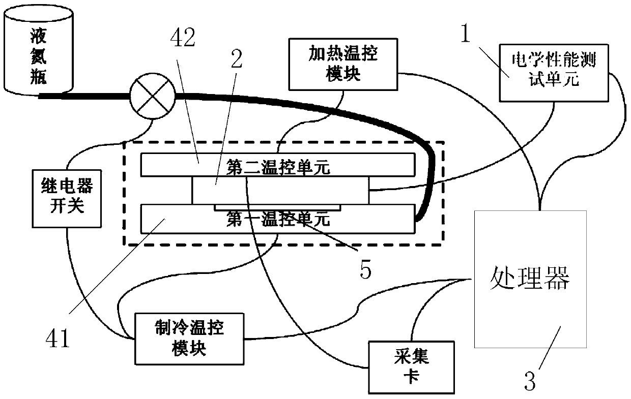
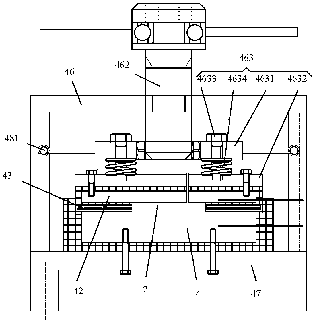
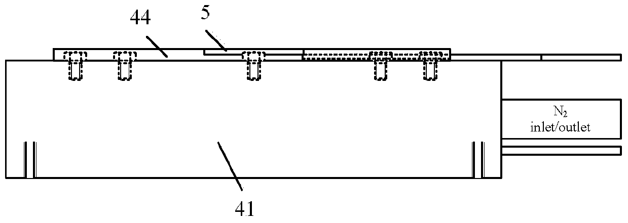
[0048] Such as Figures 1 to 4 As shown, the embodiment of the present invention provides a thermoelectric module testing system, and the testing system includes an electrical performance testing unit 1 , a heat flux detection unit and a processor 3 . The electrical performance testing unit 1 is electrically connected with the thermoelectric module 2 in the power generation state to test the output power P of the thermoelectric module 2 and the current I and internal resistance R under the output power. The heat flux detection unit, the heat flux detection unit includes a heat flux Q arranged at the cold end of the thermoelectric module for detecting the cold end of the thermoelectric module c1 The heat flow sensor 5. The processor 3 is electrically connected to the electrical performance testing unit 1 to receive the information detected by the electrical performance testing unit 1, and the processor 3 is electrically connected to the heat flux detection unit to receive the ...

no. 2 example

[0096] The improvement of the second embodiment to the first embodiment is that the test system further includes a heat flow guiding unit 6 arranged between the cold end of the thermoelectric module 2 and the first plane.

[0097] The heat flow guide unit 6 is used to direct the heat flow at the cold end of the thermoelectric module 2 to the first temperature control unit 41 after passing through the heat flow sensor 5 . The heat flow guide unit 6 effectively avoids the loss of heat flow, so that all the heat flow at the cold end of the thermoelectric module 2 flows through the heat flow sensor 5, which is conducive to narrowing the gap between the heat flow measured by the heat flow sensor 5 and the real heat flow, and improving The test accuracy of the test system.

[0098] Such as Figure 6 As shown, the heat flow guiding unit 6 includes a heat conducting sheet 61 and a first heat insulating board 62 . The heat conducting sheet 61 is arranged between the cold end of the t...


PUM


Abstract

The invention provides a testing system and a testing method of a thermoelectric module. The testing system comprises an electrical property testing unit, a thermal flux detecting unit and a processor; the electrical property testing unit is electrically connected with the thermoelectric module at the power generation operation state so as to test the output power of the thermoelectric module as well as current and internal resistance during the operation with the output power; the thermal flux detecting unit comprises a heat flux sensor which is arranged at the cold end of the thermoelectric module and is used for detecting the heat flux of the cold end of the thermoelectric module; the processor is electrically connected with the electrical property testing unit so as to receive information detected by the electrical property testing unit; the processor is electrically connected with the heat flux detecting unit so as to receive the heat flux Qc1 of the cold end of the thermoelectric module, which is detected by the flux testing unit, and is used for calculating the thermoelectric conversion efficiency of the thermoelectric module according to the formula Eta=P / (Qc1+P-1 / 2I2R). By adopting the technical scheme provided by the invention, the thermoelectric conversion efficiency of the thermoelectric module is detected.

Description

technical field [0001] The invention relates to the field of thermoelectric module testing, and more specifically, to a thermoelectric module testing system and a thermoelectric module testing method. Background technique [0002] Existing test systems generally can only test the electrical output performance of the thermoelectric module under a certain temperature condition, but cannot obtain the thermoelectric conversion efficiency. [0003] The mechanical pressure when the thermoelectric module is fixed may affect its performance, and the most suitable pressure conditions for different thermoelectric modules are generally different. This is an important but often overlooked factor in testing. Existing test setups are usually fixed clamping force. [0004] The parallelism of the upper and lower contact surfaces of the thermoelectric module will have a great impact on the quality of the thermal contact, which will determine the accuracy of the temperature test results. E...

Claims


Application Information

Patent Timeline
Patent Type & Authority Applications(China)
IPC IPC(8): G01N25/20G01R31/00
Inventor 金安君刘大为李启明彭文博许世森
Owner HUANENG CLEAN ENERGY RES INST
Learn More